Do you have a question about the Goodman A/GPG13 M SERIES W/R410A and is the answer not in the manual?
| Refrigerant | R-410A |
|---|---|
| SEER Rating | 13 |
| Voltage | 208/230 V |
| Phase | 1 |
| Sound Level | 76 dB |
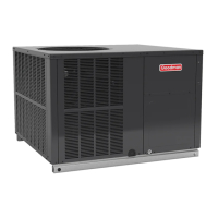
| Type | Air Conditioner |
| Series | M SERIES |
Essential guidelines for unit installation personnel.
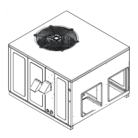
Specific requirements for installing the unit at ground level.
Procedures for verifying gas piping integrity and safety.
Description of the unit's heating cycle sequence.
Steps for initiating the unit's heating operation.
Procedure for measuring the incoming gas supply pressure.
Steps to measure and adjust gas manifold pressure.
Interpreting diagnostic codes from the ignition control.
Troubleshooting common heating operational faults.
Diagnosing issues related to the integrated ignition control.
Identifying causes for external lockout conditions.
Troubleshooting common cooling operational faults.
Understanding and addressing compressor short cycling delays.
Instructions for maintaining the unit's air filters.
Electrical schematic for specific PG13 models.
Interpreting diagnostic status light codes for troubleshooting.