EasyManua.ls Logo

Goodman GPG 16 M Series User Manual

Goodman GPG 16 M Series
32 pages
To Next Page IconTo Next Page
Page #1 background imageLoading...
Page #1 background image






Prior to installation, thoroughly familiarize yourself with this
Installation Manual. Observe all safety warnings. During in-
stallation or repair, caution is to be observed.
It is your responsibility to install the product safely and to
educate the customer on its safe use.
RECOGNIZE THIS SYMBOL AS A SAFETY PRECAUTION.
These installation instructions cover the outdoor installation
of self contained package air conditioners and heating units.

information regarding accessories.
“IMPORTANT - This product has been designed and manufactured to meet ENERGY STAR®
criteria for energy eciency when matched with appropriate coil components. However,
proper refrigerant charge and proper air ow are critical to achieve rated capacity and
eciency. Installation of this product should follow the manufacturers refrigerant charging
and air ow instructions. Failure to conrm proper charge and air ow may reduce energy
eciency and shorten equipment life.”
O
NLY
PERSONNEL
THAT
HAVE
BEEN
TRAINED
TO
INSTALL
,
ADJUST
,
SERVICE
OR
REPAIR
(
HEREINAFTER
, “
SERVICE
”)
THE
EQUIPMENT
SPECIFIED
IN
THIS
MANUAL
SHOULD
SERVICE
THE
EQUIPMENT
. T
HE
MANUFACTURER
WILL
NOT
BE
RESPONSIBLE
FOR
ANY
INJURY
OR
PROPERTY
DAMAGE
ARISING
FROM
IMPROPER
SERVICE
OR
SERVICE
PROCEDURES
. I
F
YOU
SERVICE
THIS
UNIT
,
YOU
ASSUME
RESPONSIBILITY
FOR
ANY
INJURY
OR
PROPERTY
DAMAGE
WHICH
MAY
RESULT
. I
N
ADDITION
,
IN
JURISDICTIONS
THAT
REQUIRE
ONE
OR
MORE
LICENSES
TO
SERVICE
THE
EQUIPMENT
SPECIFIED
IN
THIS
MANUAL
,
ONLY
LICENSED
PERSONNEL
SHOULD
SERVICE
THE
EQUIPMENT
. I
MPROPER
INSTALLATION
,
ADJUSTMENT
,
SERVICING
OR
REPAIR
OF
THE
EQUIPMENT
SPECIFIED
IN
THIS
MANUAL
,
OR
ATTEMPTING
TO
INSTALL
,
ADJUST
,
SERVICE
OR
REPAIR
THE
EQUIPMENT
SPECIFIED
IN
THIS
MANUAL
WITHOUT
PROPER
TRAINING
MAY
RESULT
IN
PRODUCT
DAMAGE
,
PROPERTY
DAMAGE
,
PERSONAL
INJURY
OR
DEATH
.
*NOTE: Please contact your distributor or our website

manual.
This Forced Air Central Unit Design Complies With Re-
quirements Embodied In The American National Standard /
National Standard of Canada Shown Below.

Goodman Company, L.P.
19001 Kermier Rd., Waller, TX 77484
www.goodmanmfg.com
© 2015-2018, 2021 Goodman Company, L.P.
IOG-3012E
03/2021

Table of Contents

Question and Answer IconNeed help?

Do you have a question about the Goodman GPG 16 M Series and is the answer not in the manual?

Goodman GPG 16 M Series Specifications

General IconGeneral
TypePackaged Gas/Electric
Cooling CapacityUp to 16 SEER
RefrigerantR-410A
CompressorScroll
StagesSingle-Stage
Voltage208/230 V
Warranty10 Years Limited Parts Warranty
Phase1-Phase
Sound Level (Outdoor Unit)72 dB

Summary

INSTALLATION INSTRUCTIONS

INSTALLER GUIDANCE

Instructions for installers to familiarize themselves with the unit and safety.

SAFETY PRECAUTIONS

Essential safety warnings for installation and operation.

SAFETY INSTRUCTIONS

INSTALLER RESPONSIBILITIES

Specific duties and adherence required of the installing technician.

OWNER INFORMATION

Guidance for the unit owner regarding warranty and reference.

CRITICAL HAZARD WARNINGS

Warnings about fire, explosion, high voltage, and gas leaks.

SAFETY INSTRUCTIONS

CARBON MONOXIDE POISONING HAZARD

Detailed precautions to prevent carbon monoxide poisoning during operation.

GENERAL INFORMATION AND HANDLING

OPERATIONAL WARNINGS

General warnings for proper installation, repair, operation, and maintenance.

TRANSPORTATION DAMAGE PROCEDURES

Steps to inspect and report damage incurred during shipping.

UNIT LOCATION REQUIREMENTS

GENERAL SITE SELECTION

Criteria for unit placement, clearances, and environmental factors.

INSTALLATION LOCATION TYPES

Specific requirements for ground and rooftop installations.

GAS PIPING AND RIGGING

RIGGING AND LIFTING DETAILS

Safety guidelines for rigging and moving the unit.

GAS PIPING AND CONVERSION NOTES

Information on gas type, conversion kits, and pressure requirements.

GAS PIPING INSTALLATION

NATURAL GAS CONNECTION GUIDELINES

Proper practices for connecting natural gas supply lines.

GAS PIPING INTEGRITY CHECKS

Procedures for leak testing and purging gas lines.

PROPANE GAS INSTALLATION

PROPANE GAS SAFETY AND DETECTION

Essential safety measures, warnings, and detection for propane gas.

PROPANE GAS PIPING AND TANK SIZING

Guidelines for sizing and installing propane gas piping and tanks.

ELECTRICAL WIRING AND THERMOSTAT SETUP

ELECTRICAL WIRING GUIDELINES

Instructions for line voltage and low voltage wiring.

THERMOSTAT LOCATION AND WIRING

Recommended thermostat placement and connection details.

AIRFLOW, DUCTWORK, FILTERS, AND VENTING

AIRFLOW CONVERSION AND DUCTWORK DESIGN

Modifying airflow and requirements for duct systems.

FILTER SELECTION AND VENTING INSTALLATION

Guidelines for choosing filters and installing the vent system.

OPERATIONAL SEQUENCES AND DRAINS

CONDENSATE DRAIN CONNECTION

Proper connection of the condensate drain line.

HEATING AND COOLING OPERATION SEQUENCES

Step-by-step descriptions of heating and cooling cycles.

STARTUP, ADJUSTMENTS, AND CHECKS

HEATING STARTUP PROCEDURE

Steps for initiating the heating system safely.

SAFETY CONTROL VERIFICATION

Checking rollout protection and limit controls.

PRE-OPERATION AND GAS SYSTEM CHECKS

Verifying gas supply, manifold pressure, and overall readiness.

GAS PRESSURE MEASUREMENT AND CHECKS

GAS INLET PRESSURE TESTING

Procedures for measuring and adjusting gas inlet pressure.

MANIFOLD PRESSURE TESTING

Procedures for measuring and adjusting manifold gas pressure.

PERFORMANCE VERIFICATION

GAS INPUT AND FLAME CHECKS

Verifying gas input rate and burner flame characteristics.

TEMPERATURE RISE AND STATIC PRESSURE

Measuring temperature rise and external static pressure.

BLOWER ADJUSTMENTS AND STARTUP PROCEDURES

BLOWER SPEED SETTINGS

Adjusting blower speeds for optimal airflow and temperature rise.

LIMIT CONTROL AND SHUTDOWN CHECKS

Testing safety limits and performing unit shutdown.

COOLING STARTUP AND REFRIGERANT CHARGING

Steps for initiating cooling and ensuring proper refrigerant charge.

REFRIGERANT SUPERHEAT AND SUBCOOLING

SUPERHEAT MEASUREMENT AND ADJUSTMENT

Procedures for checking and adjusting refrigerant superheat.

SUBCOOLING MEASUREMENT

Procedures for checking refrigerant subcooling.

COOLING OPERATION AMBIENT NOTES

Guidance for cooling operation at low ambient temperatures.

TROUBLESHOOTING HEATING SYSTEM FAULTS

IGNITION CONTROL AND LOCKOUT DIAGNOSTICS

Identifying and resolving ignition control failures and lockouts.

PRESSURE SWITCH AND LIMIT FAULT RESOLUTION

Diagnosing issues with pressure switches and limit controls.

GAS VALVE AND FLAME DETECTION ISSUES

Troubleshooting gas valve operation and flame detection faults.

TROUBLESHOOTING AND MAINTENANCE GUIDELINES

LOW FLAME SIGNAL AND COOLING SYSTEM FAULTS

Addressing low flame signals and compressor protection faults.

REFRIGERANT PRESSURE SWITCH TROUBLESHOOTING

Diagnosing high pressure and loss of charge switch operations.

ROUTINE MAINTENANCE TASKS

Procedures for filter, cabinet finish, and coil maintenance.

BURNER AND FLUE MAINTENANCE PROCEDURES

FLUE PASSAGE INSPECTION AND CLEANING

Steps for inspecting and cleaning the unit's flue passages.

BURNER FLAME VISUAL CHECK

How to visually inspect the burner flame for proper operation.

BURNER ASSEMBLY CLEANING

Detailed instructions for cleaning the burner assembly.

UNIT PARTS AND ACCESSORIES

SHEET METAL ACCESSORIES INFORMATION

Details on purchasing and installing sheet metal accessories.

FUNCTIONAL PARTS LISTING

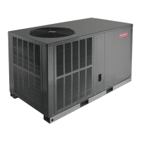
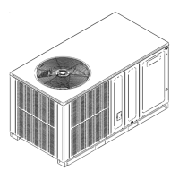
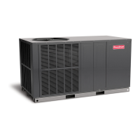
A catalog of the unit's key functional components.

ORDERING REPLACEMENT PARTS

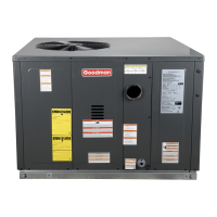
Guidance on providing unit information for part orders.

APPENDIX: DIAGNOSTICS AND TIMING CHARTS

IGNITION CONTROL DIAGNOSTIC INDICATOR CHART

Reference chart for interpreting ignition control error codes via LED signals.

HEATING AND COOLING TIMING DIAGRAMS

Visual representations of operational timing for heating and cooling cycles.

UNIT DIMENSIONS AND DUCT OPENINGS

UNIT DIMENSIONS SPECIFICATIONS

Table detailing the physical dimensions for each unit model.

DUCT OPENING SIZES

Table listing the supply and return duct opening dimensions by model.

WIRING DIAGRAM AND ELECTRICAL DETAILS

UNIT WIRING DIAGRAM

The comprehensive electrical schematic for the unit.

WIRING CODES AND COMPONENT LEGEND

Explanation of wire colors, symbols, and component abbreviations.

INSTALLATION CLEARANCES AND FILTER SIZING

MINIMUM INSTALLATION CLEARANCES

Required clearances around the unit for safety and service access.

RECOMMENDED FILTER SIZE GUIDE

Table specifying appropriate filter sizes for different unit capacities.

BLOWER PERFORMANCE DATA TABLES

BLOWER PERFORMANCE DATA BY MODEL

Detailed tables of blower performance (CFM, Watts, Rise) for each unit model.

HOMEOWNER MAINTENANCE RECOMMENDATIONS

ROUTINE MAINTENANCE PROCEDURES

Recommended tasks for system upkeep by homeowners and servicers.

PRE-CALLING A SERVICER CHECKLIST

Preliminary troubleshooting steps before contacting a service technician.

START-UP CHECKLIST

PRE START-UP VERIFICATION ITEMS

A checklist of tasks to complete before initial unit operation.

START-UP DATA RECORDING

ELECTRICAL AND PRESSURE READINGS

Fields for recording electrical, static pressure, and gas pressure data.

TEMPERATURE AND REFRIGERANT READINGS

Fields for recording temperature, superheat, and subcooling data.

Related product manuals