10
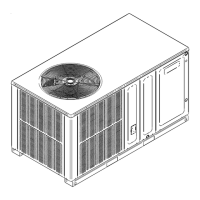
Sizing Between Single or Second Stage Regulator and Appliance*
Maximum Propane Capacities Listed are Based on 1/2" W.C. Pressure Drop at
11" W.C. Setting. Capacities in 1,000 BTU/HR
3/8" 1/2" 5/8" 3/4" 7/8" 1/2" 3/4" 1" 1-1/4" 1-1/2"
10 49 110 206 348 539 291 608 1,146 2,353 3,525
20 34 76 141 239 368 200 418 788 1,617 2,423
30 27 61 114 192 296 161 336 632 1,299 1,946
40 23 52 97 164 253 137 284 541 1,111 1,665
50 20 46 86 146 224 122 255 480 985 1,476
60 19 42 78 132 203 110 231 436 892 1,337
80 16 36 67 113 174 94 198 372 764 1,144
100 14 32 59 100 154 84 175 330 677 1,014
125 12 28 52 89 137 74 155 292 600 899
150 1
1 26 48 80 124 67 141 265 544 815
200 10 22 41 69 106 58 120 227 465 697
250 9 19 36 61 94 51 107 201 412 618
300 8 18 33 55 85 46 97 182 374 560
350 7 16 30 51 78 43 89 167 344 515
400 7 15 28 47 73 40 83 156 320 479
*DATA IN ACCORDANCE WITH NFPA PAMPHLET NO. 54
NOMINAL PIPE SIZE,
SCHEDULE 40
TUBING SIZE, O.D., TYPE L
PIPE OR
TUBING
LENGTH,
FEET
has good air circulation.
Movement of air must not be obstructed by furniture, door,
draperies, etc. The thermostat must not be mounted where
television, etc. Consult the Instruction Sheet packaged with
thermostat for mounting instructions.
All units have two stages of heating and two stages of me-
chanical cooling. Units which will have economizers may
use thermostats with two or three stages of cooling. All units
can use single stage or multi-stage thermostats. Refer to
The units are designed for operation on 60 hertz current and
at voltages as shown on the rating plate. All internal wiring
in the unit is complete. It is necessary to bring in the power
supply to the contactor as shown on the unit wiring diagram
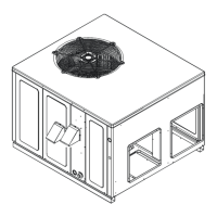
which is supplied with each unit. The low voltage wiring must
be connected between the unit control panel and the room
thermostat.
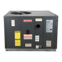
To use a single stage thermostat, move jumper located to the
left of the terminal strip labeled “Stage Delay” from NONE to
“5” or “10” minutes. This selection will cause the control to
shift to HIGH STAGE. This option controls both cooling and
heating modes. If the jumper is not moved, only low-stage
cool and low-stage heat will operate.
Refer to the unit wiring diagram for electrical connections.
When installed, the unit must be electrically grounded in ac-
cordance with local codes or in the absence of local codes,
with the National Electrical Code, ANSI/NFPA No. 70, and/
or the CSA C22.1 Electrical Code. Ensure low voltage con-
nections are waterproof.
R C W1
W2
G Y1 Y2
R
Y2
C Y1
W1
G
W2
Integrated
Control Module
Thermostat
Two-Stage Heating
with
Two-Stage Cooling
5 MINUTE DELAY
PERIOD WITH
JUMPER IN THIS
POSITION
10 MINUTE DELAY
PERIOD WITH
JUMPER IN THIS
POSITION
 Loading...