17
expansion valve, charge the system to sub-cooling, range
shown on chart, when necessary, adjust expansion valve
stem for superheat setting.
Refrigerant gas is considered superheated whenever its
temperature is higher than the saturation temperature cor-
responding to its pressure. The degree of superheat equals
the degrees of temperature increase above the saturation
temperature at existing pressure.
1. Run system at least 10 minutes to allow pressure to
stabilize.
2.
near compressor with adequate contact and insulate
for best possible reading.
3. Refer to the superheat table provided for proper sys-
tem superheat. Add charge to lower superheat or re-
cover charge to raise superheat.
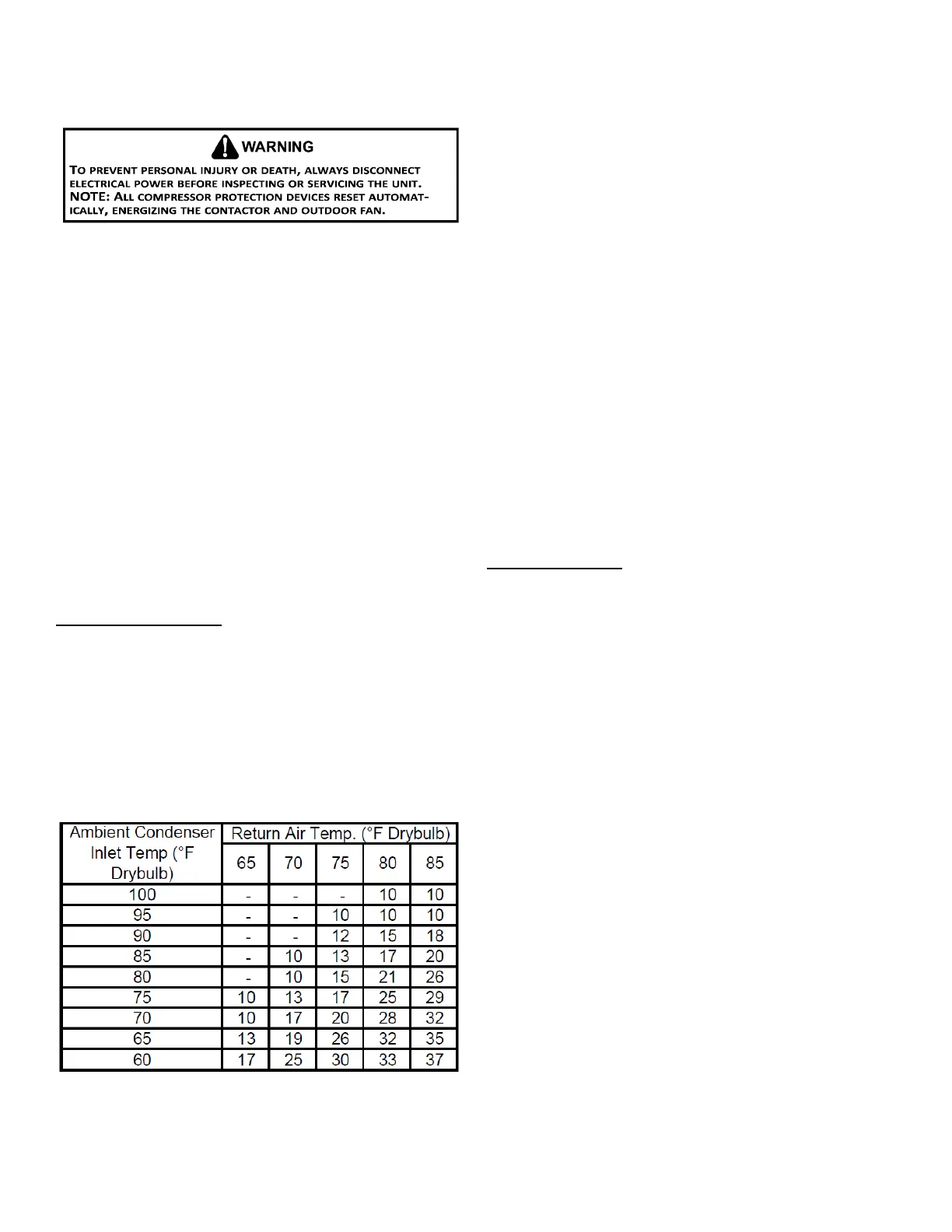
The expansion valve will not need adjustment for
most applications. Ensure system superheat is set within
range listed on chart below.
Unscrew the cover from the expansion valve, locate the
-
Replace adjustment cap. Wait a minimum of 10 minutes be-
tween adjustments to allow time for the TXV and pressures
to stabilize.
Refrigerant liquid is considered subcooled when its tem-
perature is lower than the saturation temperature corre-
sponding to its pressure. The degree of subcooling equals
the degrees of temperature decrease below the saturation
temperature at the existing pressure.
1. Attach an accurate thermometer or preferably a ther-
mocouple type temperature tester to the liquid line
close to the pressure switch.
2. Install a high side pressure gauge on the liquid access
3. Record the gauge pressure and the temperature of the
line.
4.
pressure to temperature conversion is the amount of
subcooling.
a. Liquid Line Pressure = 417
b. Corresponding Temp. °F. = 120°
c. Thermometer on Liquid line = 109°F.
To obtain the amount of subcooling, subtract 109°F from
-
tion sheet or technical information manual for the design
subcooling range for your unit.
: Mechanical cooling cannot be reliably provided at
ambient temperatures below 50° F.
1. Turn on the electrical power supply to the unit.
2. Place the room thermostat selector switch in the COOL
-
3. Set the room thermostat to the desired temperature.
The following presents probable causes of questionable unit
operation. Refer to Diagnostic Indicator Chart for an inter-
pretation of the signal and to this section for an explanation.
Remove the control box access panel and note the num-
Chart for an interpretation of the signal and to this section
for an explanation.
The ignition control is equipped with a momentary push-but-
ton switch that can be used to display on the diagnostic
feature. Depress the push-button switch for approximately
2 seconds. Do not hold for longer than 4 seconds.
Holding the button for 4 seconds or higher will erase the
most recent fault to the least recent fault.
 Loading...