15
Range Nominal
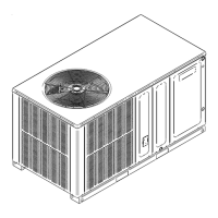
Low Stage 1.7 - 2.3" w.c. 2.0" w.c.
High Stage 3.2 - 3.8" w.c. 3.5" w.c.
Low Stage 5.7 - 6.3" w.c. 6.0" w.c.
High Stage 9.7 - 10.3" w.c. 10.0" w.c.
For Natural gas to LP gas conversion, Conversion
Kit “LPM-08” must be used. Consult your dealer for appro-
To measure the gas input use a gas meter and proceed as
follows:
1.
unit.
2. With the unit operating, time the smallest dial on the
meter for one complete revolution. If this is a 2 cubic
foot dial, divide the seconds by 2; if it is a 1 cubic foot
dial, use the seconds as is. This gives the seconds per
cubic foot of gas being delivered to the unit.
3. INPUT = GAS HTG VALUE x 3600 / SEC. PER CUBIC
FOOT
Natural gas with a heating value of 1000 BTU per
cubic foot and 36 seconds per cubic foot as determined by
Step 2, then:
Input = 1000 x 3600 / 36 = 100,000 BTU per Hour.
BTU content of the gas should be obtained from the
gas supplier. This measured input must not be greater than
shown on the unit rating plate.
4.
all pilot burners are operating.
-
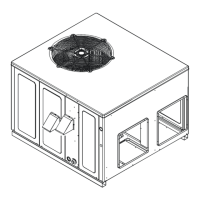
Check the temperature rise through the unit by placing ther-
mometers in supply and return air registers as close to the
unit as possible. Thermometers must not be able to sample
temperature directly from the unit heat exchangers, or false
readings could be obtained.
1. All registers must be open; all duct dampers must be in
operated for 15 minutes before taking readings.
2. The temperature rise must be within the range speci-
between supply and return air.
With a properly designed system, the proper amount of tem-
perature rise will normally be obtained when the unit is op-
erated at rated input with the recommended blower speed.
If the correct amount of temperature rise is not obtained,
it may be necessary to change the blower speed. A higher
blower speed will lower the temperature rise. A slower blow-
er speed will increase the temperature rise.
Blower speed MUST be set to give the correct air tem-
perature rise through the unit as marked on the rating plate.
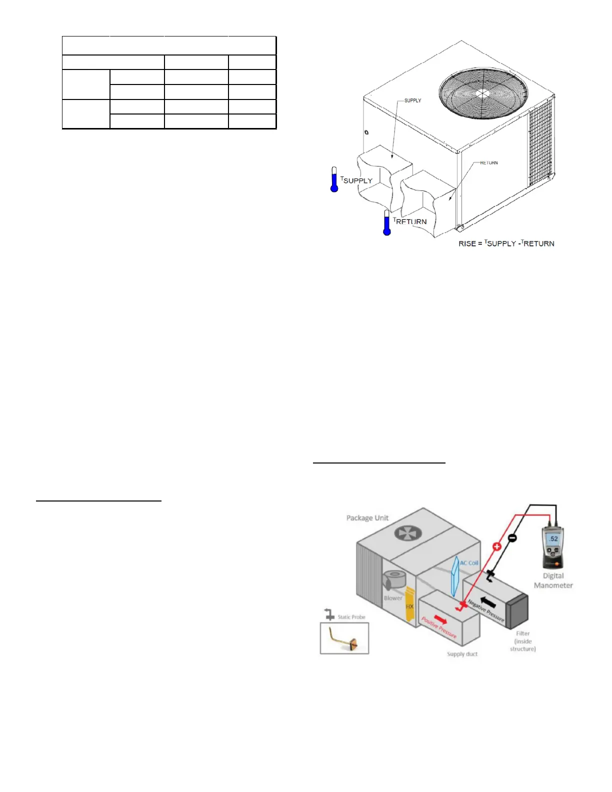
The total external static pressure must be checked on this
1. Using a digital manometer measure the static pres-
2. -
3. Add the two readings together.
Both readings may be taken simultaneously and
read directly on the manometer if so desired.
 Loading...