EasyManua.ls Logo

Goodman GPG10 - User Manual

Goodman GPG10
20 pages
Print Icon
To Next Page IconTo Next Page
Loading...
INSTALLATION & OPERATING
INSTRUCTIONS for
GPG10 & GPG12
SINGLE PACKAGE GAS-ELECTRIC
HEATING & COOLING UNIT
Affix this manual and Users Information Manual adjacent to the unit.
US
This Forced Air Central Unit Design Complies With
Requirements Embodied in The American National
Standard / National Standard of Canada Shown Below.
ANSI Z21.47-CSA-2.3 Central Furnaces
RECOGNIZE THIS SYMBOL AS A SAFETY PRECAUTION.
ATTENTION INSTALLING PERSONNEL
Prior to installation, thoroughly familiarize yourself with this Installation Manual. Observe all safety warnings. During
installation or repair, caution is to be observed.
It is your responsibility to install the product safely and to educate the customer on its safe use.
These installation instructions cover the outdoor
installation of single package gas electric heating and
cooling units. See the Product Data Book applicable to
your model* for information regarding accessories.
'NOTE: Please contact your distributor or our
website for the applicable product data
book referred to in this manual.
10-245
Goodman Manufacturing Company, L.R
2550 North Loop West, Suite 400, Houston, TX 77092
www.qoodmanmfg.com
©2004 Goodman Manufacturing Company, L.R
6/04
Question and Answer IconNeed help?

Do you have a question about the Goodman GPG10 and is the answer not in the manual?

Summary

Replacement Parts

Ordering Parts

Instructions for ordering replacement parts for the unit.

Safety Instructions

Instructions for the Installer

Guidance for installers on unit safety and specific installation requirements.

Information for the Owner

Key warranty and safety information for unit owners.

Unit Location

General Installation Requirements

Guidelines for unit placement, clearances, and environmental considerations.

Ground Level Installations

Specific requirements for installing the unit on a ground-level base.

Rooftop Installations

Requirements for ensuring roof structural integrity and safe placement.

Roof Curb Installations

Instructions for installing roof curbs and ductwork for rooftop units.

General Information

Transportation Damage Inspection

Procedures for inspecting the unit for damage upon delivery.

Rigging Details

Roof Curb Installation Rigging

Guidance on safely rigging and lowering the unit onto a roof curb.

Gas Piping

Inlet Gas Pressure Specifications

Required inlet pressure for natural and propane gas.

High Altitude Derate

How altitude affects unit performance and derating procedures.

Piping Requirements

Guidelines for gas supply piping material, size, and connections.

Gas Piping Checks

Procedures for leak testing gas connections and verifying pressures.

Propane Gas Installations

Propane Gas Tanks and Piping

Information on propane conversion, tank sizing, and piping.

Electrical Wiring

Thermostat Location Guidelines

Recommendations for optimal thermostat placement for accurate readings.

Unit Voltage and Transformer

Details on unit voltage operation and transformer connections.

Heat Anticipator Setting

How to set the heat anticipator for proper heating cycles.

Circulating Air and Filters

Airflow Conversion for Ductwork

Converting unit airflow for horizontal or down-discharge applications.

Horizontal Airflow Duct Covers

Instructions for removing panels for horizontal duct configurations.

Down Discharge Ductwork

Requirements for ductwork installation in down-discharge applications.

Filter Requirements and Installation

Importance of filters and guidelines for their placement and size.

Venting

Flue Hood Installation

Steps for installing the flue hood and bug screen.

Condensate Drain

Condensate Drain Connection

How to connect the condensate drain line and ensure a proper seal.

Normal Sequences of Operation

Heating Sequence

Step-by-step operation of the unit during heating mode.

Cooling Sequence

Step-by-step operation of the unit during cooling mode.

Fan Only Sequence

Operation when only the fan is activated by the thermostat.

Startup, Adjustments, and Checks

Heating Startup and Checks

Procedures for initial heating startup and operational checks.

Heat Anticipator Setting

How to set the heat anticipator for optimal heating performance.

Rollout Protection Control

Function and location of the rollout protection safety device.

Secondary Limit Control

Operation and purpose of the secondary limit control.

Pre-Operation Checks

Essential checks to perform before operating the unit.

Main Burner Flame Check

How to visually inspect and verify main burner flame characteristics.

Temperature Rise Check

Procedure for measuring and verifying air temperature rise.

Blower Speed Adjustments

How to adjust blower speed for correct temperature rise.

External Static Pressure Check

Method for checking external static pressure to ensure proper airflow.

Limit Check

Verifying the operation of safety limit controls.

Unit Shutdown Procedure

Steps for safely shutting down the unit.

Cooling Startup

Compressor Protection Devices

Overview of built-in safety features for compressor protection.

Cooling Refrigerant Charging

Guidelines for checking and adjusting refrigerant charge for cooling.

Troubleshooting

Ignition Control Error Codes

Interpreting diagnostic LED flashes for troubleshooting ignition issues.

Abnormal Heating Operation

Diagnosing and resolving heating problems like internal faults and lockouts.

Pressure Switch Stuck Open

Troubleshooting causes for a stuck-open pressure switch.

Pressure Switch Stuck Closed

Troubleshooting causes for a stuck-closed pressure switch.

Open Thermal Protection Device

Diagnosing issues related to open thermal protection devices.

Flame Detected with Gas Valve Closed

Identifying and resolving faults where flame is sensed with the gas valve off.

Abnormal Cooling Operation

Diagnosing and resolving cooling problems like short cycling.

Short Cycle Compressor Delay

Understanding and troubleshooting the compressor's short cycle delay.

Maintenance

Cleaning the Outside Coil

Instructions for cleaning the outdoor coil for optimal performance.

Condenser, Evaporator, and Motors

Information on lubrication for various unit motors.

Flame Sensor Maintenance

How to clean and maintain the flame sensor for reliable ignition.

Flue Passage Maintenance

Inspecting and cleaning flue passages for safe operation.

Cleaning Flue Passages

Detailed steps for cleaning the unit's flue passages.

Main Burner Flame Inspection

Visual checks for the main burner flame during heating season.

Cleaning the Burners

Step-by-step instructions for cleaning the unit's burners.

Accessories and Functional Parts

Sheet Metal Accessories

Information on available sheet metal accessories for the unit.

Functional Parts List

A list of internal components and their part names.

Ignition Control Diagnostic Indicator Chart

Heating Timing Chart

Visual representation of the heating cycle timing for various components.

Cooling Timing Chart

Visual representation of the cooling cycle timing for various components.

Unit Dimensions

Single Stage Wiring Diagram

Minimum Clearances

Recommended Filter Sizes

A chart listing recommended filter sizes based on unit tonnage.

Overview

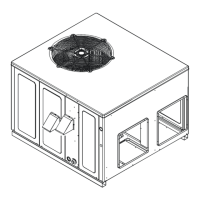
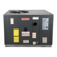
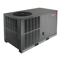
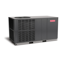
This document is an installation and operating manual for Goodman Manufacturing Company's GPG10 and GPG12 single package gas-electric heating and cooling units. It covers various aspects from installation and startup to maintenance and troubleshooting.

Function Description:

The GPG10 and GPG12 units are single package gas-electric heating and cooling systems designed for outdoor installation. They provide both heating (gas-fired) and mechanical cooling functions for conditioned spaces. The heating section utilizes an electronic ignition device to automatically light the main burners and a power vent blower to exhaust combustion products. The cooling section uses R-22 refrigerant and includes a piston flowrator expansion device. The units are designed to comply with requirements embodied in the American National Standard / National Standard of Canada (ANSI Z21.47-CSA 2.3 Central Furnaces).

Important Technical Specifications:

  • Gas Type: Factory set for natural gas, convertible to LP gas with a factory-authorized conversion kit (LPT-OOA).
  • Inlet Gas Pressure (Natural Gas): Minimum 5.0" W.C., Maximum 10.0" W.C.
  • Inlet Gas Pressure (Propane): Minimum 11.0" W.C., Maximum 13.0" W.C.
  • Manifold Pressure (Natural Gas): 3.2 to 3.8 inches W.C. (3.5 nominal) with burners operating.
  • Manifold Pressure (Propane Gas): 9.7 to 10.3 inches W.C. (10.0 nominal) with burners operating.
  • Electrical Power: Designed for 60 hertz current, 208V or 230V operation (transformer primary lead and induced draft blower motor leads may need reconnection for 208V).
  • Refrigerant: Factory charged with R-22.
  • Minimum Return Air Temperature (Heating): 50°F.
  • Maximum Return Air Temperature (Heating): 100°F.
  • Minimum Cooling Ambient Temperature: Mechanical cooling cannot be reliably provided below 50°F ambient.
  • Clearances: Minimum 12" from sides, 3" from top, and 48" for service access. Specific clearances to combustible materials are also provided.
  • Recommended Filter Sizes: Vary by unit tonnage:
    • 2 Ton: (1)20 x 20 x 1
    • 2 1/2 Ton: (1)20 x 25 x 1
    • 3 Ton: (1)25 x 25 x 1
    • 3 1/2 - 4 Ton: (2)20 x 20 x 1
    • 5 Ton: (2)20 x 25 x 1

Usage Features:

  • Installation Flexibility: Can be installed on ground level (with a concrete base) or rooftops (with structural support and a roof curb).
  • Airflow Conversion: Units can be easily converted from horizontal to down-discharge airflow delivery.
  • Electronic Ignition: Automatic ignition for main burners, eliminating the need for manual lighting.
  • Safety Controls: Equipped with various safety devices including:
    • Rollout Protection Device: Manual reset control located on the burner bracket, opens if flames are not properly drawn into the heat exchanger.
    • Secondary Limit Control: Automatic reset control on the blower scroll assembly, opens due to elevated temperatures (e.g., blower failure).
    • Primary Limit Switch: Opens if supply air temperatures are excessive (e.g., dirty filter, insufficient airflow).
    • Compressor Protection Devices: Components designed to protect the compressor against abnormal operating conditions.
    • Short Cycle Compressor Delay: Built-in feature to prevent damage from short cycling, delaying compressor output for three minutes after power restoration.
  • Diagnostic Indicator Chart: An LED on the ignition control board provides diagnostic error codes (flashes) to help identify operational issues such as internal control failure, external lockout, pressure switch problems, thermal protection device open, or flame detected with gas valve closed.
  • Adjustable Heat Anticipator: Set on the room thermostat to optimize heating cycles and prevent temperature overshooting.
  • Adjustable Heat Fan OFF Delay: Approximately 120/135/150 seconds (factory set at 150) to transfer residual heat from the heat exchanger.
  • Cooling Fan Operation: Indoor fan continues to run for approximately 60 seconds after the thermostat is satisfied to transfer additional cooling from the indoor coil.

Maintenance Features:

  • Routine Inspections: Recommended annual inspection and service by a qualified servicer.
  • Filter Replacement/Cleaning: Although not supplied with the unit, a return air filter system is required. Filters should be inspected every two months (or more frequently depending on local conditions). Throwaway filters should be replaced, and permanent filters washed, dried, and treated with adhesive.
  • Cabinet Finish Maintenance: Use a fine grade automotive wax to maintain the cabinet's high luster, especially in direct sunlight.
  • Outside Coil Cleaning (Qualified Servicer Only): Annually inspect and clean the finned areas of the coil to remove lint, hair, and debris.
  • Motor Lubrication: Condenser, evaporator, and induced draft motors have permanently lubricated bearings and do not require additional oiling.
  • Flame Sensor Cleaning (Qualified Servicer Only): Clean annually with steel wool to remove invisible coating that can reduce flame current.
  • Flue Passage Inspection and Cleaning (Qualified Servicer Only): Inspect at the start of each heating season and clean if necessary. This involves removing the burner assembly, flue, and collector box cover, then using a wire brush to clean the heat exchanger tubes.
  • Main Burner Flame Check (Qualified Servicer Only): Visually check flames annually for stability, color (soft blue, no yellow tips), and proper extension without curling, floating, or lifting off.
  • Burner Cleaning: Involves shutting off power and gas, removing the manifold and burners, cleaning burner inserts with a bottle brush, and reassembling.
  • Temperature Rise Check: Verify the temperature rise through the unit (difference between supply and return air) is within the range specified on the rating plate. Blower speed adjustments may be necessary to achieve the correct temperature rise.
  • External Static Pressure Check: Must be checked to ensure proper airflow.
  • Cooling Refrigerant Charging: Check unit charge and refrigerant superheat at the compressor to ensure proper operation for the intended application.

Goodman GPG10 Specifications

General IconGeneral
BrandGoodman
ModelGPG10
CategoryAir Conditioner
LanguageEnglish

Related product manuals