EasyManua.ls Logo

Goodman A/GPG13 M SERIES User Manual

Goodman A/GPG13 M SERIES
36 pages
To Next Page IconTo Next Page
Page #1 background imageLoading...
Page #1 background image
Affix this manual and Users Information Manual adjacent to the unit.
INSTALLATION & OPERATING
INSTRUCTIONS for
A/GPG13 M SERIES W/R410A
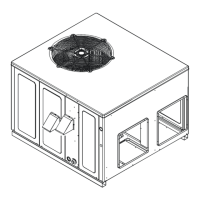
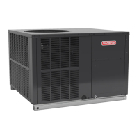
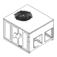
SINGLE PACKAGE GAS-ELECTRIC
HEATING & COOLING UNIT
C
US
®
Goodman Manufacturing Company, L.P.
IO-357A 5151 San Felipe, Suite 500, Houston, TX 77056
3/10 www.goodmanmfg.com
© 2009 - 2010 Goodman Manufacturing Company, L.P.
*NOTE: Please contact your distributor or
our website for the applicable
Specification Sheet or Technical Manual
referred to in this manual.
This Forced Air Central Unit Design Complies With
Requirements Embodied in The American National
Standard / National Standard of Canada Shown Below.
ANSI Z21.47•CSA-2.3 Central Furnaces
RECOGNIZE THIS SYMBOL AS A SAFETY PRECAUTION.
ATTENTION INSTALLING PERSONNEL
Prior to installation, thoroughly familiarize yourself with this Installation Manual. Observe all safety warnings. During
installation or repair, caution is to be observed.
It is your responsibility to install the product safely and to educate the customer on its safe use.
These installation instructions cover the outdoor
installation of single package gas electric heating and
cooling units. See the Specification Sheet or Technical
Manual applicable to your model* for information
regarding accessories.

Table of Contents

Question and Answer IconNeed help?

Do you have a question about the Goodman A/GPG13 M SERIES and is the answer not in the manual?

Goodman A/GPG13 M SERIES Specifications

General IconGeneral
BrandGoodman
ModelA/GPG13 M SERIES
CategoryAir Conditioner
LanguageEnglish

Summary

Safety Instructions and Warranty

Installer Guidelines

Installer must familiarize themselves with manual for specific installation requirements.

General Safety Warnings

Critical Safety Precautions

Essential warnings covering product use, fire/explosion risks, and environmental hazards.

Unit Location

Specific Location Hazards

Warnings about construction heater use, high voltage, combustible storage, and CO poisoning.

Unit Location (Continued)

General Information

Rigging Details

Gas Piping

Gas Piping (Continued)

Gas Piping Checks and Leak Testing

Procedures for leak testing gas connections and ensuring proper pressure.

Propane Gas Installations

Propane Gas Safety and Equipment

Requirement for gas detecting devices and conversion kits for propane installations.

Electrical Wiring

Electrical Wiring (Continued)

Unit Voltage and Wiring Connections

Instructions for connecting power supply and thermostat wiring to the unit.

Circulating Air and Filters

Venting and Condensate Drain

Normal Sequences of Operation

Heating, Cooling, and Fan Modes

Step-by-step description of heating, cooling, and fan-only operational sequences.

Startup, Adjustments, and Checks

Startup, Adjustments, and Checks (Continued)

Gas Supply Pressure Measurement

Inlet Gas Supply Pressure Verification

Procedure for measuring and verifying inlet gas supply pressure against specifications.

Gas Manifold Pressure Measurement and Adjustment

Manifold Pressure Specifications and Adjustment

Required manifold gas pressures for adjustment and verification.

Gas Manifold Pressure Measurement and Adjustment (Continued)

Blower Speed Adjustments

Instructions for adjusting blower speed for optimal airflow and performance.

Troubleshooting

Ignition Control Error Codes

Guide to interpreting diagnostic LED flashes for troubleshooting ignition issues.

Heating Abnormal Operation

Causes and solutions for abnormal heating operations, including internal control failures.

Troubleshooting (Continued)

Diagnostic Fault Code Interpretation

Explains fault codes for ignition failure, limit switches, and pressure switches.

Maintenance

Ignition Control Diagnostics

Diagnostic Indicator Chart and Error Codes

Guide to interpreting diagnostic LED flashes for troubleshooting ignition issues.

Operational Timing Charts

Appendix

Wiring Diagrams

Single Phase Wiring Diagram PG13(24,30,36,42)1

Schematic illustrating electrical connections for specific single-phase units.

Wiring Diagrams (Continued)

Troubleshooting Status Light Codes

Guide to interpreting the control board status light for fault diagnosis.

Wiring Diagrams (Continued)

Single Phase Wiring Diagram PG13(48,60)1

Schematic illustrating electrical connections for specific single-phase units.

Three Phase Wiring Diagram GPG13(36)3

Schematic illustrating electrical connections for specific three-phase units.

Three Phase Wiring Diagram GPG13(48,60)3

Schematic illustrating electrical connections for specific three-phase units.

Minimum Clearances and Filters

Related product manuals