8
D’installation de ce générateur de chaleur à des altitudes
-
ment auxinstructions accompagnant la trousse de conver-
sion pour haute altitude fournie avec cet appareil.
The gas/electric units naturally derate
can cause poor combustion and equipment failure. At all alti-
tudes, the manifold pressure must be within 0.3 inches W.C.
of that listed on the nameplate for the fuel used. At all alti-
tudes and with either fuel, the air temperature rise must be
within the range listed on the unit nameplate. Contact your
to the Installation Manual provided with the high altitude kit
for altitude adjustments.
No changes are required up to 2,000 feet. Use the
appropriate high altitude kit above 2,000 feet.
To avoid possible unsatisfactory opera-
do not undersize the natural/propane gas piping from the
meter/tank to the unit. When sizing a trunk line, include all
appliances on that line that could be operated simultaneously.
The rating plate is stamped with the model number, type of
gas and gas input rating. Make sure the unit is equipped to
operate on the type of gas available. The gas line installa-
tion must comply with local codes, or in the absence of local
codes, with the latest edition of the National Fuel Gas Code
NFPA 54/ANSI Z223.1.
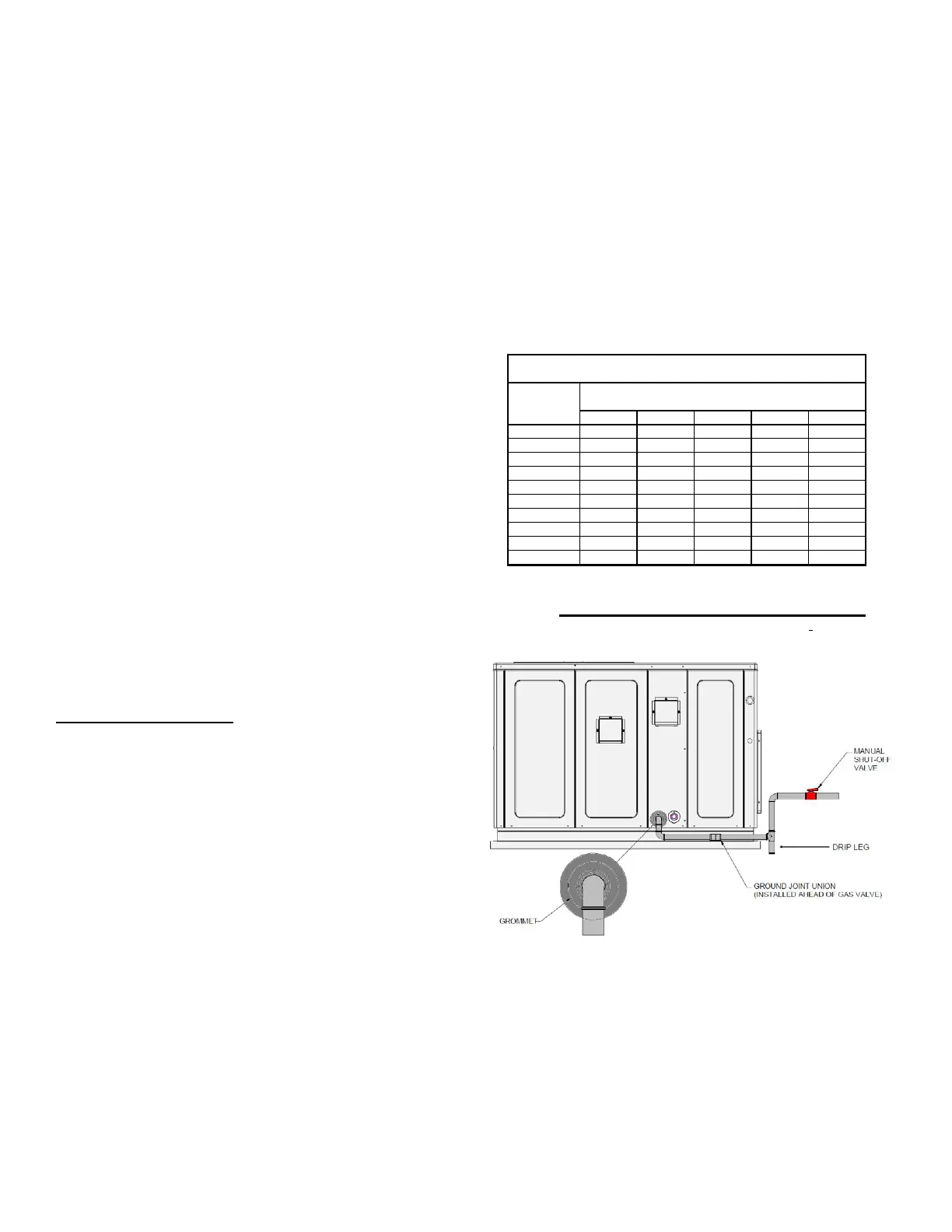
Refer to the Proper Piping Practice drawing for the general
layout at the unit. The following rules apply:
1.
-
mitted as long as it is in agreement with local codes.
2. Use pipe joint compound on male threads only. Pipe
joint compound must be resistant to the action of the
fuel used.
3. Use ground joint unions.
4. Install a drip leg to trap dirt and moisture before it can
enter the gas valve. The drip leg must be a minimum of
three inches long.
5. Use two pipe wrenches when making connection to the
gas valve to keep it from turning.
6.
7. Tighten all joints securely.
8. The unit must be connected to the building piping by
one of the following methods:
•
• -
• Listed gas appliance connectors used in accordance
with the terms of their listing that are completely in the
same room as the equipment
• In the prior two methods above the connector or tubing
must be protected from physical and thermal damage.
Aluminum alloy tubing and connectors must be coated
to protect against external corrosion when in contact
with masonry, plaster or insulation or are subject to re-
-
The unit gas supply entrance is factory sealed with
plugs. Keep plugs in place until gas supply is ready to be
installed. Once ready, replace the plugs with the supplied
grommets and install gas supply line.
Len
th of
Pipe in Feet
1/2 3/4
1
1 1/4 1 1/2
10 132 278 520 1050 1600
20 92 190 350 730 1100
30 73 152 285 590 980
40 63 130 245 500 760
50 56 115 215 440 670
60 50 105 195 400 610
70 46 96 180 370 560
80 43 90 170 350 530
90 40 84 160 320 490
100 38 79 150 305 460
Pressure = .50 PSIG or less and Pressure Drop of 0.3" W.C. (Based
on 0.60 Specific Gravity Gas)
Natural Gas Capacity of Pipe
in Cubic Feet of Gas Per Hour (CFH)
Nominal Black Pipe Size (inches)
BTUH Furnace Input
Heatin
Value of Gas
BTU/Cubic Foo t
CFH =
There will be air in the gas supply line after testing for leaks
on a new installation. Therefore, the air must be bled from
the line by loosening the ground joint union until pure gas is
has been dissipated in the air. Be certain there is no open
is placed in operation by closing the main electrical discon-
nect switch for the unit.
 Loading...