RECOGNIZE THIS SYMBOL
AS A SAFETY PRECAUTION.
ATTENTION INSTALLING PERSONNEL
Prior to installation, thoroughly familiarize yourself with this Installation Manual.
Observe all safety warnings. During installation or repair, caution is to be observed.
It is your responsibility to install the product safely and to educate the customer on its safe use.
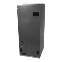
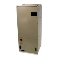
ARUF**14**/ARPT**14**
1 Important Safety Instructions
The following symbols and labels are used throughout this
manual to indicate immediate or potential safety hazards. It
is the owner’s and installer’s responsibility to read and com-
ply with all safety information and instructions accompanying
these symbols. Failure to heed safety information increases
the risk of personal injury, property damage, and/or product
damage.
ASPT**14**/ASUF**14**
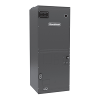
AIR HANDLERS INSTALLATION & OPERATING INSTRUCTIONS
Contents
1 Important Safety Instructions .................................. 1
2 Shipping Inspection ................................................. 2
2.1 Parts ........................................................................3
2.2 Handling ..................................................................3
3 Codes & Regulations................................................ 3
4 Replacement Parts ................................................... 3
5 Pre-Installation Considerations .............................. 3
5.1 Preparation ..............................................................3
5.2 System Matches ......................................................3
5.3 Interconnecting Tubing ............................................3
5.4 Clearances ..............................................................3
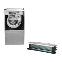
5.5 Horizontal Applications ............................................4
6 Installation Location ................................................ 4
6.1 Upflow Installation....................................................4
6.2 Horizontal Left Installation .......................................4
6.3 Downflow/Horizontal Right Installation ....................5
7 Refrigerant Lines ...................................................... 7
7.1 Tubing Size ..............................................................7
7.2 Tubing Preparation ..................................................7
7.3 Special Instructions .................................................8
7.4 Tubing Connections for Flowrator Model .................8
7.5 Tubing Connections for TXV Models .......................8
8 Condensate Drain Lines........................................... 9
9 Ductwork ................................................................... 9
9.1 Return Ductwork ......................................................9
10 Return Air Filters .................................................. 10
11 Electric Heat .......................................................... 10
12 Electrical and Control Wiring............................... 12
12.1 Building Electrical Service Inspection .................. 12
12.2 Wire Sizing..........................................................12
12.3 Maximum Overcurrent Protection (MOP) ............12
12.4 Electrical Connections – Supply Voltage .............13
12.4.1 Air Handler Only (Non-Heat Kit Models) ....13
12.4.2 Air Handler - Non-Circuit Breaker Heat Kits .....13
12.4.3 Air Handler With Circuit Breaker Heat Kit.........13
12.5 Low Voltage Connections ....................................13
12.5.1 Thermostats ....................................................13
12.6 Speed Tap Adjustment.........................................13
13 Achieving 2% Low Leakage Rate ........................ 14
14 Start-Up Procedure ............................................... 14
15 Regular Maintenance............................................ 14
16 Airflow Data .......................................................... 15
21 Wiring Diagrams................................................... 21
IO-427K
10/2014