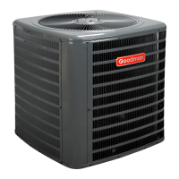
5
5000
4500
4000
3500
3000
2500
2000
1500
1000
500
0 1 2 3 4 5 6 7 8 9
10
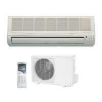
LEAK(S)
PRESENT
MINUTES
V
ACUUM
IN
MICRONS
CONDENSIBLES OR SMALL
LEAK PRESENT
NO LEAKS
NO CONDENSIBLES
E
LECTRICAL
C
ONNECTIONS
HIGHVOLTAGE!
D
ISCO NNECT
ALL
POWER
BEFORE
SER V ICING
.
M
ULTIPLE
POWER
SOURCES
MAY
BE
PRESEN T
.F
AILURE
TO
DO
SO
MAY
CAUSE
PROPE RTY
DAMAGE
,
PERSO NAL
INJU R Y
OR
DEATH
DUE
TO
ELECT R IC
SHOCK
.W
IRIN G
MUST
CONF O RM
WITH
NEC
OR
CEC
AND
ALL
LOCAL
CODE S
.U
NDERSIZED
WIRES
COU L D
CAUSE
POOR
EQU IP MENT
PERFORMANCE
,
EQU IP MENT
DAMAGE
OR
FIRE
.
WARNING
T
O
AVOID
THE
RISK
OF
FIRE
OR
EQU IP MENT
DAMAGE
,
USE
COPPER
CONDUCT O RS
.
WARNING
U
NITS
WITH
RECIPROCAT ING
COM PRESS ORS
AND
NON
‐
BLEED
TXV’
S
REQ U IRE
A
H
ARD
S
TAR T
K
IT
.
NOTICE
The condensing unit rating plate lists pertinent electrical data
necessary for proper electrical service and overcurrent protec-
tion. Wires should be sized to limit voltage drop to 2% (max.)
from the main breaker or fuse panel to the condensing unit.
Consult the NEC, CEC, and all local codes to determine the
correct wire gauge and length.
Local codes often require a disconnect switch located near the
unit; do not install the switch on the unit. Refer to the installa-
tion instructions supplied with the indoor furnace/air handler for
specific wiring connections and indoor unit configuration. Like-
wise, consult the instructions packaged with the thermostat
for mounting and location information.
O
VERCURRENT
P
ROTECTION
The following overcurrent protection devices are approved for
use.
• Time delay fuses
• HACR type circuit breakers
These devices have sufficient time delay to permit the motor-
compressor to start and accelerate its load.
H
IGH
V
OLTAGE
C
ONNECTIONS
Route power supply and ground wires through the high voltage
port and terminate in accordance with the wiring diagram pro-
vided inside the control panel cover.
L
OW
V
OLTAGE
C
ONNECTIONS
Condensing unit control wiring requires a nominal 24 VAC (+/-
6 VAC), 60 Hz, minimum 25 VA service from either the indoor
or outdoor transformer packaged with the optional CTK0* com-
municating thermostat kit. Low voltage wiring for the condens-
ing units depends on the thermostat used. The unit is de-
signed to work as part of a fully communicating HVAC system
utilizing the ComfortNet™, CTK0* thermostat, ComfortNet com-
patible indoor unit, and up to four wires. The unit also has
legacy 24 VAC inputs to support non-communicating systems.
Route control wires through the low voltage port and terminate
in accordance with the wiring diagram provided inside the con-
trol panel cover.
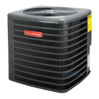
HIGH
VOLTAGE
PORT
LOW
VOLTAGE
PORT
Voltage Ports
NOTE: If the condensing unit is wired in the communicating
mode together with the compatible communicating indoor unit
and thermostat, then the communicating thermostat is able to
search and identify the condensing unit when power is applied
to the system. Refer to the Installation Manual of the
communicating thermostat for more information.
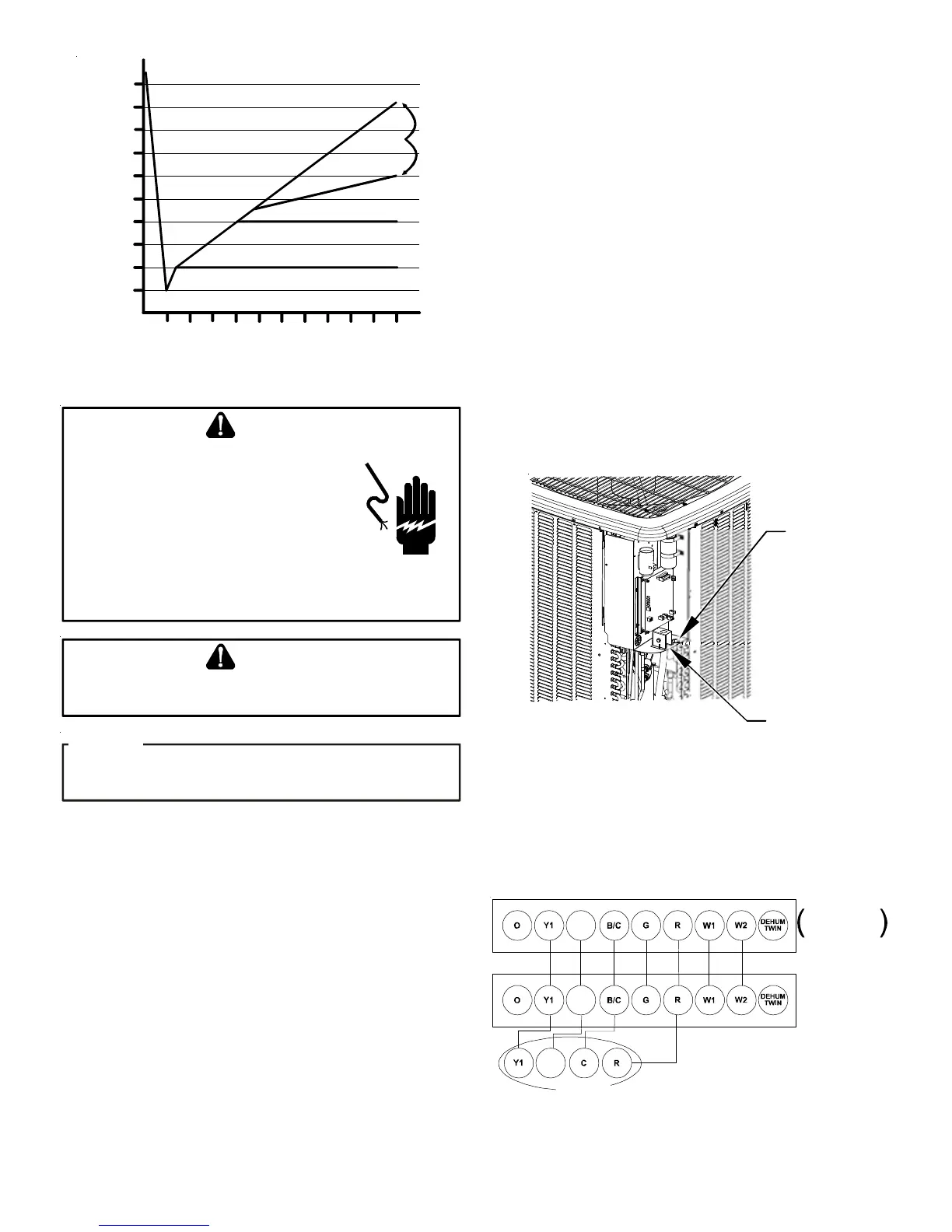
Y2
Y2
OD UNIT
FURNACE OR
IR HANDLER
Thermostat
Two-Stage Heating
with
Two-Stage Cooling
Y2
Two-Stage Non-Communicating Thermostat
Low Voltage Wire Connection (legacy mode)