Do you have a question about the Goodman MSG-12CRN1N and is the answer not in the manual?
Guidelines and warnings for consumers and service personnel regarding safe operation.
Understanding safety symbols, words, and labels to prevent hazards and ensure safe operation.
Procedures and precautions for safely handling refrigerants to prevent injury or environmental damage.
Critical safety instructions and best practices for unit installation to prevent hazards.
Best practices for operating the unit safely to prevent damage or injury.
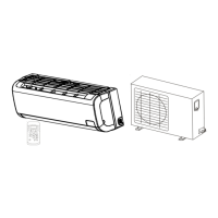
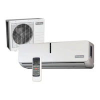
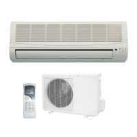
Detailed list of functionalities and capabilities of the indoor unit.
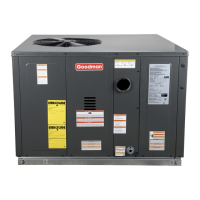
Detailed list of functionalities and capabilities of the outdoor unit.
Physical dimensions and measurements for the indoor unit in inches and mm.
Physical dimensions and measurements for the outdoor unit in inches and mm.
Diagrams and explanation of the refrigerant flow in cooling and heat pump modes.
Defines the temperature ranges for cooling and heating operations.
Overview of remote control performance, features, and display panel functions.
Detailed explanation of each button on the remote control and its effect.
Explanation of the symbols and indicators shown on the remote control's LCD display.
Instructions for using the remote control, including battery replacement and automatic operation.
Torque wrench specs, cable connection sizes, and pipe length/elevation guidelines.
Steps for system evacuation and gas charging with R-410A refrigerant.
Details on the electronic control system's functions, protections, and operating parameters.
Explanation of unit protections, cooling, heating, and defrost modes.
Description of forced operations, sleep mode, auto-restart, and turbo mode functions.
Flowcharts to diagnose issues for 12k, 18k, and 24k models.
Steps for resolving control board resets and indoor fan speed problems.
Guidance for diagnosing sensor errors, compressor overcurrent, and EEROM faults.
Troubleshooting steps for outdoor unit failures and communication errors.
Electrical schematic for the indoor unit's components and connections.
Electrical schematic for the outdoor unit's components and connections.
This document provides service instructions for Goodman Split System Wall Mounted Air Conditioners and Heat Pumps with R-410A Refrigerant. It is intended for qualified, professionally trained HVAC technicians.
The device offers a range of functions and features designed for comfort and ease of use. Key functions include ON/OFF operation via remote control, room temperature sensing and control, and a starting temperature control with a 5-second delay for the indoor fan at startup. For safety, it incorporates a time delay safety control with an approximate restart time of 3 minutes.
Users can adjust the indoor fan speed to high, medium, low, or breeze settings. Operation indication lamps provide visual feedback for each mode. The unit features a 2-direction air vane, with louver direction automatically determined by the operation mode. A sleep mode auto control sets the fan to low speed (cooling/heating) and turns off after 7 hours. Independent dehumidification is available for high humidity conditions. The unit also includes a self-diagnosing function that operates in any mode. Airflow direction can be manually set or automatically swung up or down. An auto mode automatically adjusts to the room temperature. The anti-cold function prevents cold air bursts at the beginning of unit startup. Temperature compensation, defrost mode, and auto-restart functions further enhance its operation. For 12k models, a Turbo function allows the unit to reach the preset temperature in the shortest time during cooling mode. Flexible wiring connections and an easy-clean panel contribute to convenient installation and maintenance.
The outdoor unit features a power relay control with a 3-minute delay between continuous ON/OFF operations. A low noise airflow system, utilizing a bird tail propeller fan, ensures quieter operation. Hydrophilic aluminum fins are used in both cooling and heating modes to improve heating efficiency. A reversing valve operates in heating mode, except during defrosting. An anti-rust cabinet, crafted from electrolytic zinc steel sheet metal and anti-rust coated components, ensures durability. A valve protection cover protects the valves and prevents water from dripping.
The remote control offers comprehensive functionality. It supports operating modes such as AUTO, COOL, DRY, HEAT (for heat pump models), and FAN. Timer setting functions allow for scheduling up to 24 hours. The indoor temperature setting range is 62°F - 88°F (17°C-31°C). A full function LCD display provides clear information. Buttons include TEMP for adjusting temperature, MODE for selecting operation mode, SWING for changing louver angle, RESET for canceling settings, AIR DIRECTION for horizontal swing louvers, LED DISPLAY for clearing/illuminating the digital display, FAN SPEED for adjusting fan speed, ON/OFF for power, TIMER ON/OFF for scheduling, LOCK for locking current settings, and TURBO for rapid cooling (12k models only).
The display panel of the indoor unit provides visual indicators: a digital display area for temperature and timer settings, a transmission indicator that flashes when the remote control transmits signals, an ON/OFF indicator, an operation mode indicator, a lock indicator, a timer display indicator, and a fan speed indicator.
For automatic operation, users can turn the power on, select AUTO mode, set the desired room temperature, and press ON/OFF. The unit will logically choose COOL, FAN, or HEAT based on the difference between ambient and set temperatures. Manual selection of COOL/HEAT/FAN modes is also possible.
The device incorporates several protection features to ensure reliability and longevity. These include a 3-minute delay for compressor restarting, open circuit sensor protection, and fan speed sensor protection (shutting down if indoor fan speed is too low or high). It also has start protection, which shuts down the unit if the compressor attempts to start four times within 5 minutes, and overcurrent protection for the compressor.
In cooling mode, the compressor, outdoor fan, and indoor fan (at low, medium, or high speed depending on temperature difference) activate. If the indoor coil temperature drops too low, the compressor and outdoor fan turn off, while the indoor fan continues to run. For heat pump models, if the outdoor coil temperature gets too high, the compressor and outdoor fan turn off.
In dehumidifying mode, the indoor fan runs at low speed, with indoor coil temperature protection similar to cooling mode.
In heating mode (for heat pump models), the reversing valve is energized. Upon a call for heating, the compressor and outdoor fan turn on. The indoor fan delays for a short period to reduce "cold-blow" before ramping up. The compressor runs for a minimum of 7 minutes. If the indoor coil temperature rises too much, the compressor and fans turn off.
Defrost mode is initiated when the outdoor coil temperature stays below 30°F (-1°C) for over 3 minutes or is less than 32°F (0°C) for 90 minutes of heating operation. Defrost terminates when the outdoor coil temperature rises to 68°F (20°C) or after 10 minutes. During defrost, the compressor and outdoor fan initially turn off, then the indoor fan turns off after 10 seconds. The reversing valve shifts, and 5 seconds later the compressor turns back on. Near the end of the defrost cycle, the compressor shuts off for 25 seconds, then the outdoor fan turns on. Just before the compressor turns back on, the reversing valve shifts back to heating mode, and the compressor turns back on. The indoor fan turns back on when the indoor coil reaches a predetermined temperature.
Automatic changeover mode operates by turning on heating if the room temperature is about 1.8°F (1.0°C) below the set point, or cooling if it's 1.8-3.6°F (1.0-2.0°C) above the set point. If the room temperature is close to the set point, the unit runs in fan-only mode. Once a mode is active, it will not switch for at least 15 minutes. The directional louvers' motion should be set appropriately for the operational mode.
Forced cooling operation can be activated, running the unit continuously for 30 minutes regardless of indoor temperature. After 30 minutes, the set point becomes 75°F (24°C), and the unit operates in dehumidifying mode, maintaining all cooling and dehumidifying mode protections. Forced automatic operation sets the temperature to 75°F (24°C).
The sleep mode function is available for cooling, heating, or automatic modes. The set point temperature will rise (cooling) or drop (heating) by about 1.8°F (1.0°C) per hour for 2 hours, then the low-speed indoor fan activates. After 7 total hours, the unit turns off.
An auto restart function ensures that in the event of a sudden power failure, the unit returns to its previous settings.
Maintenance involves checking for refrigerant leakage after installation or repair. The drain hose must be installed properly to ensure water drains away. The unit should be installed on a stable, level stand to prevent vibration and water leakage. The outdoor unit should be placed away from vegetation. When lifting or transporting, two people should be used. The unit should not be installed where it is directly exposed to sea coast conditions.
During operation, airflow inlets and outlets should not be blocked. Cleaning should be done with a soft cloth, avoiding harsh detergents or solvents. Caution is advised when removing the air filter due to sharp metal edges. The filter should be cleaned every two weeks or more often if necessary and securely seated. Hands and foreign objects should be kept away from air outlets during operation.
For installation, the correct size circuit breaker and fuse must be used on a dedicated circuit. The unit must be properly grounded, and extension cords should not be used. Proper ventilation of conditioned space is essential. The unit should be protected from inclement weather. The inlet grill should not be opened during operation, and electrostatic filters (if equipped) should not be touched. If smoke or unusual noises occur, the unit must be immediately turned off and all power disconnected. Water should not be allowed to enter the unit; if soaked or submerged, an authorized servicer should be contacted. If the unit is not used for a long period, all power should be disconnected. The outdoor unit should be placed away from high traffic areas, and no objects should be placed on it.
Remote control battery replacement involves sliding the back cover and installing two AAA alkaline dry batteries according to polarity. Old or different battery types should not be mixed. Batteries should be removed if the remote is not used for extended periods to prevent leakage. If leakage occurs, avoid skin contact and wash with clean water. Leaked batteries should not be used and must be disposed of properly. Average battery life is approximately 6 months. Batteries should be replaced if there is no answering beep from the indoor unit or if the transmission indicator light fails to illuminate.
| Cooling Capacity | 12, 000 BTU/h |
|---|---|
| EER | 11.5 |
| Energy Efficiency Ratio (EER) | 11.5 |
| Refrigerant | R-410A |
| Power Supply | 208/230V, 1 Phase, 60 Hz |
| Operating Temperature Range (Cooling) | 62°F - 90°F |