Do you have a question about the Goodman MSG-18HRN1W and is the answer not in the manual?
Provides crucial notices for consumers and service technicians regarding safety.
Guidelines for safely handling refrigerants, including warnings about hazards.
Emphasizes high voltage risks and general cautions for installation and operation.
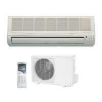
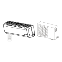
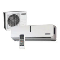
Provides detailed dimensions for the indoor unit models.
Details the dimensions for various outdoor unit models.
Diagrams illustrating the refrigerant flow in cooling and heat pump modes.
Specifies the operating temperature ranges for cooling and heating modes.
Details the performance features and operational capabilities of the remote control.
Instructions for installing and replacing batteries in the remote control.
Explains automatic, COOL, HEAT, and FAN modes using the remote control.
Specifies torque wrench settings and cable connection specifications for installation.
Provides requirements for refrigerant pipe length, elevation, and additional refrigerant.
Step-by-step guide for evacuating the system using a vacuum pump and micron gauge.
Procedure for charging the system with R-410A refrigerant using a manifold gauge set.
Details the functions and specifications of the electronic control system.
Lists features that protect the reliability and lifespan of the unit and compressor.
Describes cooling, dehumidifying, heating, defrost, and auto-changeover modes.
Covers forced modes, sleep mode, auto restart, turbo mode, and display board indicators.
Explains the meaning of indicators on the display board for 18k and 24k models.
Troubleshooting guide specific to 12K model units.
Troubleshooting guide specific to 18K and 24K model units.
Provides a step-by-step diagnostic chart for troubleshooting 12k models.
Provides a step-by-step diagnostic chart for troubleshooting 18k & 24k models.
Troubleshooting steps for frequent resetting of the outdoor control board.
Guide for diagnosing and fixing issues with unresponsive indoor fan speed on 12k models.
Diagnosing and resolving errors related to temperature sensors.
Troubleshooting steps when compressor overcurrent protection activates four times.
Information on EEROM errors indicating a defective indoor control board.
Diagnostic steps for when the outdoor unit fails to operate.
Troubleshooting steps for communication errors between indoor and outdoor units.
Table providing resistance values for temperature sensors at various temperatures.
Wiring diagram for the indoor unit of the MSG-12CRN1 model.
Wiring diagram for the outdoor unit of the MSG-12CRN1 model.
Wiring diagram for the indoor unit of the MSG-12HRN1 model.
Wiring diagram for the outdoor unit of the MSG-12HRN1 model.
Wiring diagram for the indoor units of MSG-18CRN1 and MSG-24CRN1 models.
Wiring diagram for the outdoor units of MSG-18CRN1 and MSG-24CRN1 models.
Wiring diagram for the indoor units of MSG-18HRN1 and MSG-24HRN1 models.
Wiring diagram for the outdoor units of MSG-18HRN1 and MSG-24HRN1 models.
| Model | MSG-18HRN1W |
|---|---|
| SEER Rating | 16 |
| Refrigerant | R-410A |
| Voltage | 208/230 V |
| Phase | 1 |
| Type | Split Air Conditioner |
| Cooling Capacity | 18, 000 BTU/h |
| Sound Level | 54 dB(A) |