Do you have a question about the Goodman MSG-24HRN1W and is the answer not in the manual?
Crucial notices for consumers and serivcers, including safety symbols and warnings.
Detailed guidelines for safe handling of refrigerants, including warnings and precautions.
Key safety instructions for unit installation, operation, and electrical connections.
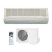
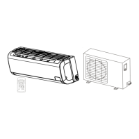
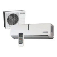
Overview of features and functions of the indoor unit.
Highlights of the design and operational features of the outdoor unit.
Physical dimensions (W x D x H) for indoor unit models in inches and mm.
Physical dimensions (W x D x H) for outdoor unit models in inches and mm.
Technical data for cooling capacity, input, SEER, and heating capacity.
Details on compressor type, brand, capacity, and fan motor specifications.
Specifications for refrigerant type, piping, pressure, and operating temperature ranges.
Visual representation of refrigerant flow in cooling-only and heat pump modes.
Defines the acceptable ambient and indoor temperature ranges for cooling and heating.
Overview of the remote control's operational capabilities and display functions.
Explanation of each button's function on the remote control.
Description of indicators on the remote control's LCD display.
Guidance on using AUTO, COOL, HEAT, and FAN modes via the remote.
Specifications for torque wrenches and power cord selection for installation.
Guidelines for refrigerant piping length, elevation, and additional refrigerant charge.
Step-by-step instructions for evacuating the refrigerant system using a vacuum pump.
Detailed process for charging the system with R-410A refrigerant.
Overview of electronic control functions and operating parameters for different voltages.
Details on unit protection, fan operation, cooling, heating, and defrost modes.
Explanation of forced cooling, auto, sleep, turbo modes, and display board indicators.
Table of indicator lights and their meaning for 12K and 18K/24K models.
Flowchart for diagnosing issues with 12k models when no indicators are lit.
Flowchart for diagnosing issues with 18k/24k models when no indicators are lit.
Procedure to diagnose and fix frequent outdoor control board resets.
Troubleshooting steps for unresponsive indoor fan speed on 12k models.
Diagnosing errors related to temperature sensors, compressor overcurrent, and EEROM.
Troubleshooting steps for when the outdoor unit fails to operate.
Steps to diagnose and resolve communication issues between indoor and outdoor units.
Table correlating temperature readings with resistance values for sensors.
Wiring diagrams for the indoor and outdoor units of the MSG-12CRN1 model.
Wiring diagrams for the indoor and outdoor units of the MSG-12HRN1 model.
Wiring diagrams for indoor and outdoor units of MSG-18CRN1 and MSG-24CRN1 models.
Wiring diagrams for indoor and outdoor units of MSG-18HRN1 and MSG-24HRN1 models.
| Refrigerant | R-410A |
|---|---|
| Voltage | 208/230V |
| Phase | 1 |
| Compressor Type | Scroll |
| Cooling Capacity | 24000 BTU/h |