Do you have a question about the Goodman GMP Series and is the answer not in the manual?
Important warnings regarding carbon monoxide and safe operation.
Guidelines on where the heater can and cannot be installed.
Mandates that the vent system must terminate outdoors.
Prohibits connecting to specific types of chimneys or fireplaces.
Step-by-step guide for adjusting gas supply and manifold pressures.
Distinguishes between space types affecting air requirements.
Details on providing air from indoor spaces.
Details on providing air from outdoor spaces.
Guidance on proper gas piping connections, leak checks, and strain avoidance.
Options for air supply and requirements for return air ducts.
Specifies voltage, frequency, and wiring guidelines for power connection.
Instructions for installing and positioning the thermostat.
Method for checking supply and manifold gas pressures.
Explains the function and testing of the main limit switch.
Describes the vent pressure switch and its role in operation.
Details the flame roll-out switch and its manual reset function.
Explains the flame sensor's role in the electronic ignition system.
Function of the switch that prevents operation with the blower door open.
Overview of the combined ignition module and fan control unit.
Guidance on installing, inspecting, and maintaining air filters.
Procedure to measure and adjust the temperature rise of the heater.
Instructions for maintaining the blower and venter motors.
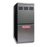
This document provides comprehensive installation and operating instructions for the GMP Power Vented Multi-Position Gas-Fired Air Heater. It is designed for use in buildings constructed on-site and must be connected to distribution ductwork. The manual emphasizes safety, proper installation, and maintenance to ensure efficient and reliable operation while preventing potential hazards such as carbon monoxide poisoning.
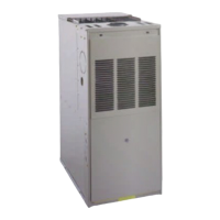
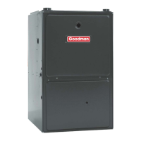
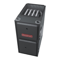
The GMP Power Vented Multi-Position Gas-Fired Air Heater is an appliance designed to provide heating for residential and commercial spaces. It utilizes gas as its fuel source and incorporates a power vent system to safely expel combustion byproducts outdoors. The multi-position design allows for flexible installation configurations to suit various building layouts. The heater is equipped with an electronic ignition system that ignites the burners upon a call for heat and controls the venter blower and circulating air blower. It is designed to operate within specified temperature rise ranges, ensuring efficient heat distribution throughout the building.
The heater is suitable for use with various gas groups, including 2H, 2L, 2E, and 3P, provided the specific country code is present on the appliance. Before installation, it is crucial to verify that local distribution conditions, gas type, pressure, and current adjustments are compatible with the appliance. The heater is factory-fitted for natural 2H gas at 20 mbar and operates on a 230V ~ 50Hz electrical supply, requiring less than 15A and 2kW.
For optimal performance and safety, the appliance must be installed indoors and protected from water. It should not be installed in mobile homes, bedrooms, bathrooms, closets, or any enclosed space accessible only through such rooms. When installed in a utility room or closet, the door opening must be wide enough to allow for easy entry of the heater or replacement of other appliances. In residential garages, the heater must be installed in a sealed enclosure with all combustion and ventilation air originating outdoors. In commercial garages, the ignition source must be above the level where flammable vapors might accumulate, and circulating ductwork must be above the level where vapor recirculation could occur. The heater must also be protected from physical damage, especially from vehicles.
The venting system is critical for safe operation and must terminate outdoors. The use of non-metallic factory vent material is prohibited. Horizontal venting is not permitted unless an optional power venter, such as the SVB-80-5, is used and local codes allow it. A vent adapter must be installed between the heater's vent connection and the field-installed vent system. Accessories that improve efficiency, like flue dampers, must be removed before installation. Horizontal vent runs must incline 20mm per meter from the heater and should not exceed 75% of the vertical runs. Support for horizontal runs is required at least every meter and at every elbow.
Proper combustion and ventilation air supply are essential. The appliance requires air from outdoors, or under certain conditions, from within the dwelling. Insufficient air can lead to dangerous conditions such as fire, explosion, property damage, or personal injury, including death. The manual defines "unconfined space" and "confined space" and provides specific requirements for air openings and ductwork based on these classifications. For installations where combustion air originates indoors, two permanent openings communicating with an additional room(s) of sufficient volume are required. For outdoor air, two permanent openings, one near the top and one near the bottom of the space, are necessary. The minimum dimension for air openings should not be less than 8cm.
Gas piping connections require careful attention. The rating plate must be checked to ensure the heater is equipped for the supplied gas type. A union and a listed manual shutoff valve must be installed outside the heater cabinet for easy control assembly removal. A plug on the supply pipe at the manual valve is needed for pressure measurement. A capped sediment trap, or drip leg, should be installed as close to the heater as possible, incorporating a change of direction of the gas flow. Gas pipes must be sized to prevent undue pressure drop and should not run through or inside circulating air ducts. Copper tubing is not recommended for natural gas installations with high hydrogen sulfide content.
Electrical supply connections require a nominal 230V, 50Hz separate supply line with a current overload device and a manual switch. Copper conductors are preferred, and wiring must have a minimum rating of 35°C temperature rise. The heater contains electronic components that require a positive earth connection, which must be provided from the main power supply or an earth ground. The gas supply pipe must never be used for grounding purposes.
Thermostat installation should follow the thermostat's instructions, with wiring connected as shown in the wiring diagram. The thermostat should be located near the return air grille, approximately 1.27m from the floor, and away from heat sources like hot water pipes, lamps, or direct sunlight.
The circulating air supply can be drawn from outside the building, return ducts from several rooms, a central return, or a combination thereof. Return air from one dwelling unit should not be discharged into another. Return air should not be taken from bathrooms, kitchens, heater rooms, garages, utility or laundry rooms, or cold areas. If outside air is used, it should not be taken within 2.54m of an appliance vent outlet or plumbing drainage system, or within 1m above an exhaust system discharge. The circulating air ducts must be completely and positively sealed to prevent combustion products, including carbon monoxide, from entering the air stream. The return air duct system should be approximately equal to or greater than the area of the warm air discharge.
Annual inspections of the heater and its vent system are strongly recommended to check for separation, corrosion, or perforation. It is the contractor's responsibility to inform the user about the importance of these inspections.
Checking gas pressures is a critical maintenance step. This involves installing manometers on the supply and manifold pressure taps, shutting off other gas-fired appliances, operating the heater for 5 minutes, checking and adjusting pressures, and then restoring the system.
Safety controls, including the main limit switch, vent pressure switch, flame roll-out switch, flame sensor, and blower door interlock switch, must be checked for proper operation during start-up. The main limit switch is designed to shut off burner gas if the supply air temperature exceeds the maximum design temperature. The vent pressure switch prevents operation if the vent system is restricted. The flame roll-out switch shuts down burner gas if flames are detected outside the heat exchanger. The flame sensor ensures the presence of flame, and the blower door interlock switch disconnects electrical power if the blower door is dislodged. These controls are non-adjustable and should never be altered, jumpered, or bypassed, as this can create hazardous conditions.
Circulating air filters are crucial for maintaining air quality and preventing premature heat exchanger failure. Although the heater does not have provisions for internal filters, it is recommended to install a filter grille or filters in the return air duct(s). Filters must be inspected monthly for dirt accumulation and replaced as necessary. Operating the heater without filters for extended periods is not recommended.
Temperature rise measurement and adjustment are necessary to ensure satisfactory performance. This involves inspecting ducts for leaks, operating the heater for at least 15 minutes, measuring return and outlet air temperatures, and adjusting the circulating air blower speed tap if needed.
Motor lubrication and maintenance are also covered. The circulating air blower's sleeve bearings are permanently lubricated and require no attention. However, the exterior of the circulating air motor should be cleaned monthly, especially around the air holes, to prevent overheating from dust accumulation. Keeping air filters clean is vital to prevent restricted airflow over the motor windings. The venter motor bearings are prelubricated and require no attention.
The integrated fan/ignition control module is an electronic device that manages burner ignition, venter blower operation, and circulating air blower speeds and timings. This control is not field repairable.
The manual strongly warns against carbon monoxide poisoning and emphasizes the importance of proper ventilation, sealing of ducts, and regular maintenance to prevent combustion products from entering the living space. It also highlights that the heater is designed for installation in buildings constructed on site only and should not be used as a construction heater.
| Fuel Type | Natural Gas or Propane |
|---|---|
| Type | Gas Furnace |
| Heating Capacity | 40, 000 to 120, 000 BTU/h |
| Stages | Single Stage |
| Blower Type | Multi-Speed |
| Warranty | Limited Lifetime Heat Exchanger, 10-Year Parts |