IO137 29
GENERAL VENTING REQUIREMENTS
The requirements contained herein apply to both Category I draft hood equipped and fan as-
sisted combustion appliances. At no time should a venting system listed for a Category II, III, or
IV appliance be sized with these tables. The alternate sizing methods described in the National
Fuel Gas Code (NFPA54/ANSI Z223.1-1996) may also be used to size the venting system for
a draft hood equipped appliance. At this time, alternate sizing methods have not been devel-
oped for fan assisted appliances. Therefore, until engineering data is developed to allow alter-
nate sizing methods for Category I fan assisted appliances, the vent tables must be used.
1. The venting tables included in this instruc-
tion apply to vents and chimneys internal to
the structure below the roof line. Exterior
chimneys or vents not enclosed by the struc-
ture or chase below the roof line may experi-
ence continuous condensation depending on
locality. Consult local gas utility, appliance
manufacturer and/ or local codes. A chim-
ney with one (1) or more sides exposed to
the outside of the structure is considered to
be an exterior chimney. A type B or listed
chimney lining system passing through an
unused masonry chimney flue is not con-
sidered to be exposed to the outdoors.
2. If the vent or connector size determined from
the tables is smaller than the appliance
draft hood outlet or flue collar, the smaller
size may be used provided:
a) The total vent height “H” is at least 10 ft.
b) Vents or connectors for appliance outlets
or flue collars 12” in diameter or smaller
are not reduced more than one table
size (e.g. 12” to 10” is a one size reduc-
tion).
c) The maximum capacity listed in the tables
for a fan assisted appliance is reduced
by 10% (0.90 X maximum capacity).
d) The draft hood is greater than 4” in di-
ameter. Do not connect a 3” diameter
vent or connector to a 4” diameter draft
hood outlet. THIS PROVISION DOES
NOT APPLY TO FAN ASSISTED
APPLIANCES.
3. Single appliance venting configurations with
zero lateral lengths, Tables 1 & 2, are as-
sumed to have no elbows in the vent system.
For all other configurations, the vent system
is assumed to have two (2) 90
o
elbows. For
each additional 90
o
elbow or equivalent (two
45° elbows are equivalent to one 90
o
elbow)
beyond two, the maximum capacity listed in
the venting table should be reduced by 10%
(0.90 X maximum listed capacity).
4. The common venting Tables 3, 4, 7 & 8
were generated using a maximum horizon-
tal vent connector length of 1 1/2 feet (18”)
for each inch of connector diameter as fol-
lows;
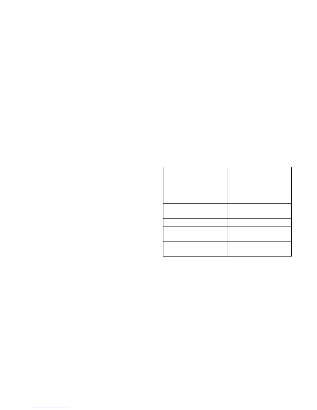
CONNECTOR
MAXIMUM
HORIZONTAL
DIA. CONNECTOR
LENGTH
3 inches 4 1/2 feet
4 inches 6 feet
5 inches 7 1/2 feet
6 inches 9 feet
7 inches 10 1/2 feet
8 inches 12 feet
9 inches 13 1/2 feet
10 inches 15 feet
The vent connector should be routed to the
vent utilizing the shortest possible route.
Connectors with longer horizontal lengths
than those listed above are possible under
the following conditions:
a) The maximum capacity (FAN MAX. OR
NAT MAX.) or the vent connector shall
be reduced 10% for each additional mul-
tiple of the length listed above. For exam-
ple, the maximum length listed above for
a 4 inch connector is 6 feet. With a connec-
tor greater than 6 feet but not exceeding
12 feet the maximum capacity must be
reduced by 10% (0.90 X maximum vent
connector capacity). With a vent connec-
tor length greater than 12 feet but not
exceeding 18 feet, the maximum capac-