EasyManua.ls Logo

Goodman GMS80403A A Series - User Manual

Goodman GMS80403A A Series
17 pages
Print Icon
To Next Page IconTo Next Page
Loading...
RT6622014r3
November 2013
This manual is to be used by qualified, professionally trained HVAC technicians
only. Goodman does not assume any responsibility for property damage or
personal injury due to improper service procedures performed by an unqualified
person.
Refer to Service Manual RS6612006for troubleshooting information.
All safety information must be followed as provided in the Service Manual.
Refer to the appropriate Parts Catalog for part number information.
Model numbers listed on page 3.
GMS8 33-3/8" 80% Gas Furnace Units
80% AFUE, Single Stage,
Multi-Speed, Upflow Horizontal
TECHNICAL MANUTECHNICAL MANU
TECHNICAL MANU
ALAL
ALAL
AL
Copyright © 2011, 2013 Goodman Manufacturing Company, L.P.
C US
®
Question and Answer IconNeed help?

Do you have a question about the Goodman GMS80403A A Series and is the answer not in the manual?

Summary

Goodman GMS8 Furnace Technical Manual

Product Identification

Model Number Breakdown

Explanation of the GMS8 model number coding system for part identification.

Model Number Listing

List of specific GMS8 furnace model numbers available.

Product Design

General Operation

Overview of the furnace's electronic ignition and self-diagnosing control module.

Location Considerations

Guidelines for furnace placement and installation environment.

Component Identification

Product Dimensions

Product Design

Pressure Switch Trip Points

Specifications for pressure switch settings for various models.

Limit Switch Settings

Settings for primary, rollout, and auxiliary limit switches.

Product Design

Coil Matches

Compatibility information for Amana brand coils with GMS8 furnaces.

Product Design

Thermostat Recommendations

Guidance on selecting compatible thermostats for the unit.

Filter Requirements

Specifications for required furnace filters and their installation.

Furnace Specifications

Blower Performance Specifications

Wiring Diagrams

Schematics

Overview

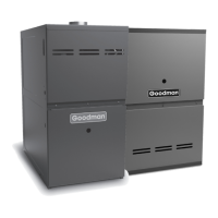
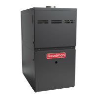
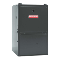
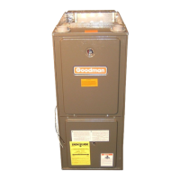
The Goodman GMS8 33-3/8" 80% Gas Furnace Units are designed for residential heating applications, offering 80% AFUE (Annual Fuel Utilization Efficiency), single-stage operation, and multi-speed capabilities for upflow and horizontal installations. These units are equipped with an electronic ignition device for burner lighting and an induced draft blower to exhaust combustion products, ensuring efficient and safe operation.

Function Description:

The GMS8 furnace operates by igniting natural gas (or propane with an optional kit) to heat air, which is then circulated throughout the building by a multi-speed blower. The induced draft blower ensures proper exhaust of combustion gases. An electronic control module manages the furnace's operations and includes a self-diagnosing feature that flashes an LED to indicate problems, aiding in troubleshooting. An interlock switch prevents operation if the inner blower door is not properly in place, enhancing safety. The furnace is designed for use with a single-stage, non-power robbing thermostat.

Important Technical Specifications:

Model Variations (GMS8A):**

  • Btuh Input (US) High Fire: Ranges from 45,000 to 140,000 Btuh.
  • Output (US) High Fire: Ranges from 36,000 to 112,000 Btuh.
  • A.F.U.E.: 80% across all models.
  • Rated External Static (" w.c.): .20 - .50.
  • Temperature Rise (°F): Ranges from 25-55 to 40-70, depending on the model.
  • High Stage Pressure Switch Trip Point (" w.c.): Ranges from -0.70 to -0.90.
  • Blower Wheel (D" x W"): Sizes include 10x6, 10x8, 10x10, and 11x10.
  • Blower Horsepower: 1/3, 1/2, or 3/4 HP.
  • Blower Speeds: 4 speeds across all models.
  • Max CFM @ 0.5 E.S.P.: Ranges from 1157 to 2131 CFM.
  • Power Supply: 115-60-1 (115 Volts, 60 Hz, Single Phase).
  • Minimum Circuit Ampacity (MCA): Ranges from 8.5 to 15.2 Amps.
  • Maximum Overcurrent Device: 15 Amps.
  • Transformer (VA): 40 VA.
  • Heat Anticipator (Amps): 0.7 Amps.
  • Primary Limit Setting (°F): Ranges from 160° to 220°.
  • Auxiliary Limit Setting (°F): 120°.
  • Rollout Limit Setting (°F): 300°.
  • Gas Supply Pressure (Natural/Propane) (" w.c.): 7/11.
  • Manifold Pressure (Natural/Propane) High Stage (" w.c.): 3.5/10.
  • Orifice Size (Natural/Propane): Varies by model (e.g., #43/#55).
  • Number of Burners: Ranges from 2 to 6.
  • Vent Connector Diameter (inches): 4 inches.
  • Shipping Weight (lbs.): Ranges from 120 to 183 lbs.

Model Variations (GMS8B):**

  • Btuh Input (US) High Fire: Ranges from 40,000 to 120,000 Btuh.
  • Output (US) High Fire: Ranges from 32,000 to 96,000 Btuh.
  • A.F.U.E.: 80% across all models.
  • Rated External Static (" w.c.): .20 - .50.
  • Temperature Rise (°F): Ranges from 20-50 to 40-70, depending on the model.
  • High Stage Pressure Switch Trip Point (" w.c.): Ranges from -0.80 to -0.90.
  • Blower Wheel (D" x W"): Sizes include 10x6, 10x8, 10x10, and 11x10.
  • Blower Horsepower: 1/3, 1/2, or 3/4 HP.
  • Blower Speeds: 4 speeds across all models.
  • Max CFM @ 0.5 E.S.P.: Ranges from 1157 to 2131 CFM.
  • Power Supply: 115-60-1.
  • Minimum Circuit Ampacity (MCA): Ranges from 8.5 to 15.2 Amps.
  • Maximum Overcurrent Device: 15 Amps.
  • Transformer (VA): 40 VA.
  • Heat Anticipator (Amps): 0.7 Amps.
  • Primary Limit Setting (°F): Ranges from 150° to 210°.
  • Auxiliary Limit Setting (°F): 120°.
  • Rollout Limit Setting (°F): 300°.
  • Gas Supply Pressure (Natural/Propane) (" w.c.): 7/11.
  • Manifold Pressure (Natural/Propane) High Stage (" w.c.): 3.5/10.
  • Orifice Size (Natural/Propane): Varies by model (e.g., #45/#55).
  • Number of Burners: Ranges from 2 to 6.
  • Vent Connector Diameter (inches): 4 inches.
  • Shipping Weight (lbs.): Ranges from 120 to 183 lbs.

Physical Dimensions (GMS8):

  • Cabinet Width: Varies (14", 17-1/2", 21", 24-1/2").
  • Height: 33-3/8".
  • Depth: 27-7/8".
  • Front Clearance: 24" unobstructed recommended for servicing.
  • Clearance to Combustible Materials (Minimum): Sides: 1", Rear: 0", Front: 3", SW Vent: 6", B Vent: 1", Top: 1".

Usage Features:

  • Upflow/Horizontal Installation: Versatile design allows for installation in various configurations.
  • Multi-Speed Blower: Provides flexibility in airflow for heating and cooling, allowing installers to adjust speeds to match specific requirements and achieve desired temperature rise and CFM.
  • High Altitude Derate: For installations above 4500 feet, the furnace rating should be reduced by 4% for every 1000 ft above sea level. Specific kits may be required for pressure switch and orifice changes to compensate for reduced air and gas density at higher altitudes.
  • Coil Matches: Compatible with a wide array of Amana® brand indoor coils (cased and uncased, with or without field-installed TXV expansion devices) for R22 and R-410A refrigerants, ensuring flexibility for complete HVAC system integration.
  • Filter Requirements: Filters are mandatory and must be provided by the installer, complying with UL900 or CAN/ULCS111 standards. Operating the unit without filters voids the warranty. Minimum filter area tables are provided for both disposable (300 ft/min face velocity) and permanent (600 ft/min face velocity) filters, for side return, bottom return, upflow, and counterflow configurations.
  • Location Considerations: Should be centralized for optimal air distribution. Must not be installed directly on carpeting, tile, or combustible wood flooring. In residential garages, burners and ignition sources must be at least 18 inches (457 mm) above the floor and protected from physical damage.
  • Venting: Category I vented, meaning it operates at non-positive pressure. Venting must comply with NFPA 54/ANSI Z223.1 (latest edition) in the US, and CAN/CSA B149.1 and CAN/CSA B149.2 (latest editions and amendments) in Canada. The vertical height of the Category I venting system must be at least as great as the horizontal length.

Maintenance Features:

  • Self-Diagnosing Electronic Control Module: An LED on the control module flashes specific sequences to indicate operational problems, simplifying troubleshooting. Refer to the Troubleshooting Chart and Abnormal Operation - Integrated Ignition Control section in the Service Manual for detailed explanations of LED codes.
  • Service Manual and Parts Catalog: Comprehensive documentation (RS6612006 for troubleshooting, and specific Parts Catalogs for part numbers) is available to assist qualified technicians with service and repairs.
  • Accessibility: A 24" unobstructed front clearance is recommended for ease of servicing.
  • Qualified Technicians: Installation and repair must be performed by qualified, professionally trained HVAC technicians meeting AHRI standards to ensure safety and proper operation. Goodman disclaims responsibility for property damage or personal injury due to improper service by unqualified persons.
  • Wiring Diagrams: Detailed wiring schematics are provided for reference, but technicians should always refer to the most up-to-date wiring diagram on the unit's serial plate. All wiring must be properly polarized and grounded, and replacement wiring must have a temperature rating of at least 105°C and use copper conductors.
  • Regular Filter Replacement: Filters are crucial for unit performance and warranty. Regular inspection and replacement are necessary.

Goodman GMS80403A A Series Specifications

General IconGeneral
BrandGoodman
ModelGMS80403A A Series
CategoryFurnace
LanguageEnglish

Related product manuals