27
Table 5. - Troubleshooting Encoded Two Stage
Cooling Thermostats Options
TEST FUNCTION SIGNAL OUT SIGNAL FAN
S
T
E
T
S1 +
* S1 - *
S1 + -
S2 +
S2 -
S2 + -
S3 +
* S3 - *
* S3 + - *
R + -
COM
LOW SPEED COOL
* LO SPEED COOL *
HI SPEED COOL
LO SPEED HEAT
O
LO SPEED HEAT
HI SPEED HEAT
G
N/A
N/A
24 VAC
GND
YCON +
* YCON - *
YCON + -
W1 HEATER
ED -
( FUTURE USE )
W1 HEATER
W2 HEATER
NONE
N/A
N/A
R TO T'STAT
COM TO T'STAT
Y1
* Y / Y2 HI *
Y / Y2
W / W1
O
W / W1
EM / W2
G
N/A
N/A
R
C1 , C2
* ERROR CONDITION ( DIODE ON THERMOSTAT BACKWARDS )
* ERROR CONDITION ( S3 CAN ONLY READ + )
INDICATION
* ERROR CONDITION ( S3 CAN ONLY READ + )
INPUT
FROM
THERMOSTAT
POWER
TO
THERMOSTAT
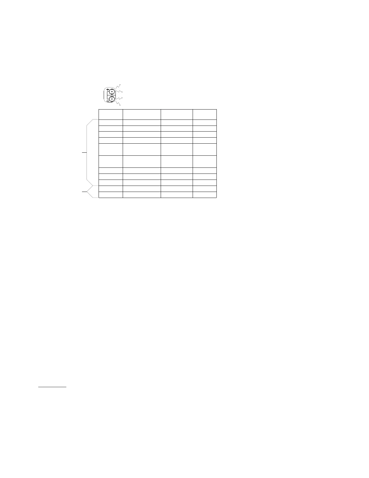
NOTES:
1.) THE TEST SPADE CAN BE CONNECTED TO ANY OTHER TEST SPADE ON EITHER BOARD.
2.) THE + LED WILL BE RED AND WILL LIGHT TO INDICATE + HALF CYCLES.
THE - LED WILL BE GREEN AND WILL LIGHT TO INDICATE - HALF CYCLES.
BOTH RED AND GREEN ILLUMINATED WILL INDICATE FULL CYCLES DENOTED BY + - .
3.) SIGNAL OUT CONDITION FOR W1 , W2 HEATER WILL BE AFFECTED BY OT1 PJ4 AND OT2 PJ2
JUMPERS AND OUTDOOR THERMOSTATS ATTACHED. THE TABLE ABOVE ASSUMES OT1 PJ4 IS
REMOVED AND OT2 PJ2 IS MADE WITH NO OUTDOOR THERMOSTATS ATTACHED.
SEE NOTE 3
SEE NOTE 3
The chart above provides troubleshooting for either version of
the encoded thermostat option. This provides diagnostic
information for the GMC CHET18-60 or a conventional two
cool / two stage heat thermostat with IN4005 diodes added
as called out in the above section.
A test lead or jumper wire can be added from the test terminal
to any terminal on the B13682-74 or B13682-71 variable
speed terminal board and provide information through the use
of the LED lights on the B13682-71 VSTB control. Using this
chart, a technician can determine if the proper input signal is
being received by the encoded VSTB control and diagnose
any problems that may be relayed to the output response of
the B13682-74 VSTM control.
Example:
The system is calling for 1
st
stage cooling operation.
The proper input signal from either thermostat op-
tion will cause the red “+” LED light to illuminate when
the test terminal and the “S1” terminal are connected
using a test lead or jumper wire. This verifies proper
input from the thermostat. The proper output is a
“YCON” signal to the RSG condensing unit. When
a test lead or jumper is connected between Test and
YCON, the red “+” LED will illuminate. The corre-
sponding response from the CKTS control will be an
illuminated “LOW” LED light and 24V applied to the
Low capacity contactor through the “LOW” terminal
output.
This similar procedure can be utilized on any termi-
nal on the VSTB controls. The chart above indicates
the proper input and LED status as well as the
corresponding out signal. Each mode of operation
must be verified during the check out procedure
when the units are installed. The LED light provides
a easy method to verify operation without the use of
a multi-meter.
 Loading...