Do you have a question about the Goodman RT6100004R13 and is the answer not in the manual?
Understand safety symbols, words, and labels for safe operation and installation.
Essential guidelines for the safe handling of refrigerants, emphasizing precautions and procedures.
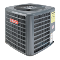
Model numbers and descriptions for R-22 Split System Air Conditioners.
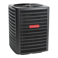
Model numbers and descriptions for R-22 Split System Heat Pumps.
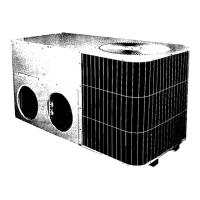
Model numbers and descriptions for Single Piece Air Handlers.
Model numbers and descriptions for MBR/MBE Air Handler units.
Model numbers and descriptions for Evaporator Coil units.
Detailed information and diagrams for Expansion Valve Kits.
Lists various accessories compatible with different coil models.
Electric heat kits designed for MBR & MBE blower applications.
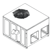
Description of the operation, components, and design of the condensing unit.
Description of coils and blower coils, covering their design and operation.
Explanation of the cooling cycle, refrigerant flow, and component functions.
Explanation of the heating cycle, reversing valve, and component functions.
Explanation of the defrost cycle operation in heat pump units.
Description and function of the AFE18-60A control board for heat pump applications.
A comprehensive chart for diagnosing cooling and heat pump issues with causes and remedies.
Procedure to check voltage at various unit terminals using a voltmeter.
Visual inspection and continuity testing of unit wiring for faults.
Steps to verify thermostat, wiring, and anticipator function.
Procedure to test the step-down transformer and control circuit.
How to test the solid-state delay-on make after break time delay relay.
Procedures for testing compressor contactors and other relay holding coils.
Testing the contacts of cooling and heating fan relays.
Diagnostics for the Comfort Alert system using LED indicators and fault codes.
Procedure to check the loss of charge protector for proper operation.
Methods for testing run and start capacitors for continuity and capacitance.
Testing PSC motor windings for continuity and ground faults.
Troubleshooting steps for ECM motors, including voltage and signal checks.
A chart to diagnose common issues with ECM blower motors.
Explanation of dipswitch functions on the MBE air handler motor control.
Checking the operation and components of GE X13TM motors.
Safety warnings and procedures for checking compressor electrical terminals.
Procedure to test compressor windings for resistance.
Steps to check the reversing valve and solenoid for proper operation.
Procedure to test the defrost control board for proper sequencing.
Detailed explanation of the heating operation for heat pump units.
Explanation of the defrost cycle operation for heat pump units.
Sequence of operation for AEP* & MBE units with single stage condensers.
Sequence of operation for AEP* & MBE units with single stage heat pumps.
General practices for repairing refrigeration systems.
Methods for leak testing refrigeration systems using nitrogen.
Procedures for properly evacuating air and moisture from the system.
Guidelines for charging the system with refrigerant, including warnings.
Information on measuring and understanding system superheat.
How to check compressor efficiency by analyzing performance test results.
Explanation of the function and operation of thermostatic expansion valves.
Symptoms and checks for overfeeding by the expansion valve.
Symptoms and checks for underfeeding by the expansion valve.
Procedure to measure and understand refrigerant subcooling.
Steps to test the operation of expansion valves.
Explanation and checks for capillary tubes and restrictor orifices.
How to identify and rectify a restricted liquid line.
Identifying and correcting issues related to refrigerant overcharge.
Identifying and removing non-condensables from the system.
Identifying compressor burnout and the steps for cleanup.
Guidelines for refrigerant piping, including length and tube sizing.
Understanding duct static pressure and its impact on system performance.
Procedure to measure air handler external static pressure for proper airflow.
How to measure static pressure drop across coils.
Wiring diagram for the AFE18-60A control board.
Wiring schematic for one-stage electric heat with OT/EHR18-60.
Wiring schematic for two-stage electric heat with OT/EHR18-60.
Wiring schematic for air handlers with electric heat.
Wiring schematic for MBR blower with electric heat.
Wiring schematic for AEPF units with electric heat.
Wiring schematic for ASPF air handlers with electric heat.
Wiring schematic for ASPF air handlers with electric heat.
| Brand | Goodman |
|---|---|
| Model | RT6100004R13 |
| Category | Air Conditioner |
| Language | English |