- 7 -
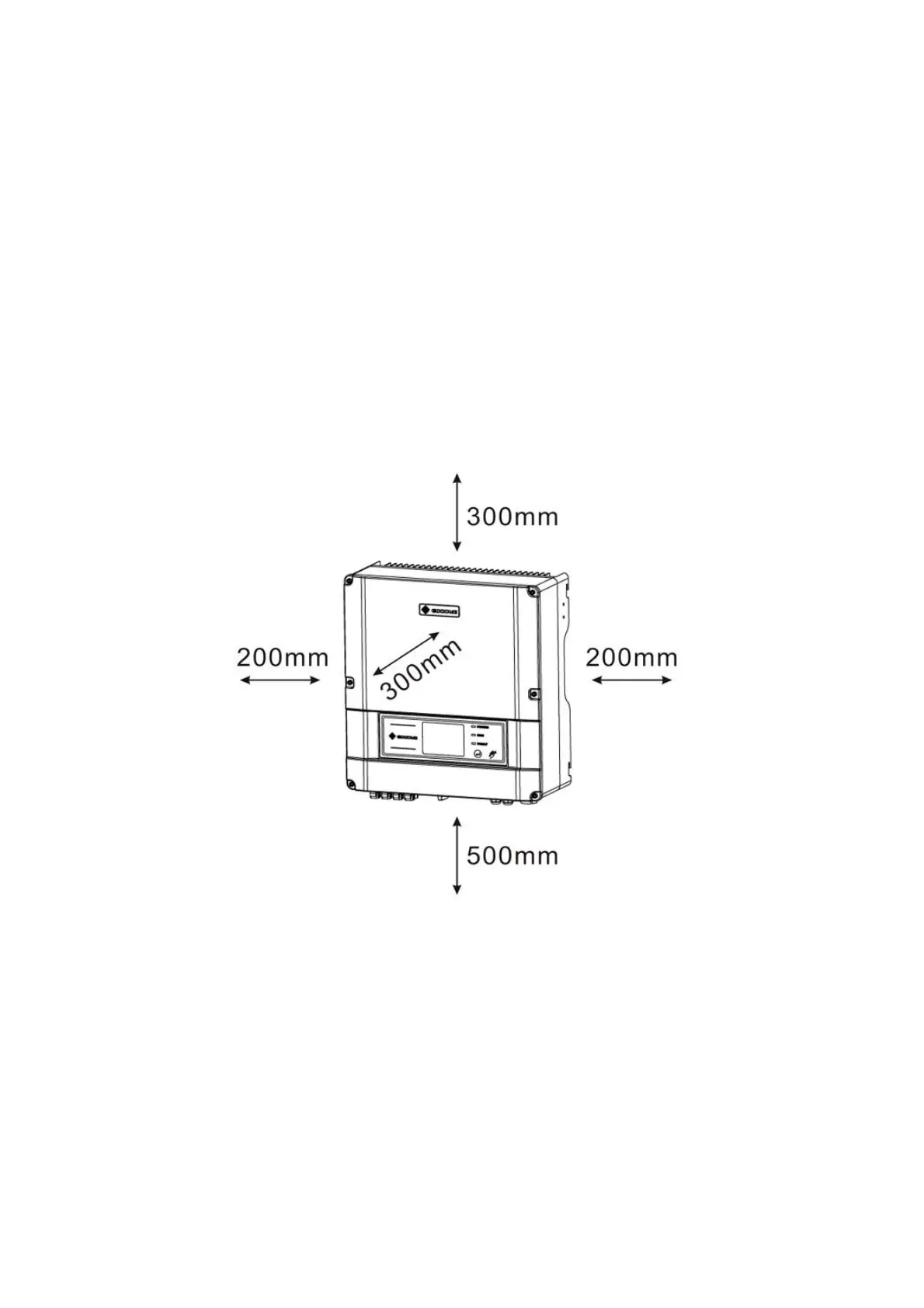
` In consideration of heat dissipation and convenient
dismantlement, the minimum clearances around the inverter
should be no less than the following value:
Upward . . . . . . . . . . . . . . . . . . . . . . . . . . . . . . . 300mm
Downward . . . . . . . . . . . . . . . . . . . . . . . . . . . . 500mm
Front . . . . . . . . . . . . . . . . . . . . . . . . . . . . . . . . 300mm
Both sides . . . . . . . . . . . . . . . . . . . . . . . . . . . . . 200mm
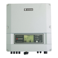
Figure 3.3.1-2
3.3.2 Mounting Procedure
A Use the wall-mounted bracket as a template and drill 7 holes
on the wall, 10 mm in diameter and 80 mm deep.
 Loading...