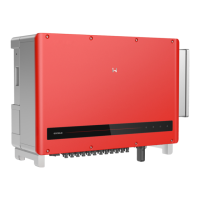
Installation instruction of VACONN series
Installation instruction of WELAND series
Fasten screw cap clockwise
Fasten screw cap clockwise
Material(Annealed copper wire)
Fastening three screws to
ensure each screw head is
not exceeding the surface
Inverter
fasten screw cap clockwise
Inverter
4mm
2
Copper Conducotr
Material (Annealed copper wire)
Fastening three screws to
ensure each screw head is not
exceeding the surface
10mm
10mm
Note:
1. Neutral conductor shall be blue, line conductor shall be black or brown (preferred), protective
earth bonding line shall be yellow-green.
2. Fix (moment: 0.6N.m) the connector of AC cable to the corresponding terminals.
AC cable illustration :
A
B
C
Value
10~12mm
2.5~4mm²
10mm around
Grade
A
B
C
Description
O.D
Section area of conduction material
Length of Bare wire
Annealed Copper Wire
4.3.2 AC Circuit Breaker And Residual Current Protection Device
In order to ensure that the inverter can be safe and reliable to disconnect from the power grid
please install an independent two pole circuit breaker to protect the inverter.
The inverter can exclude the possibility of DC residual currents to 6mA in the system, where an
external RCD is required in addition to the build-in RCMU, type A can be used, type B or type A
must be used to avoid tripping.
Inverter model
GW1000-NS / GW1500-NS / GW2000-NS / GW2500-NS
GW3000D-NS / GW3600D-NS
GW4200D-NS / GW5000D-NS
GW6000D-NS
Recommended circuit breaker specifications
16A
25A
32A
40A
Note: Multiple inverter are not allowed to share a circuit breaker.
The integrated leakage current detection device of the inverter can detect can detect external
leakage current in real time. When the detected current exceeds the limit value, inverter will
quickly disconnect from the grid, if the leakage current protection device is installed externally,
the action current should be 300mA or higher.
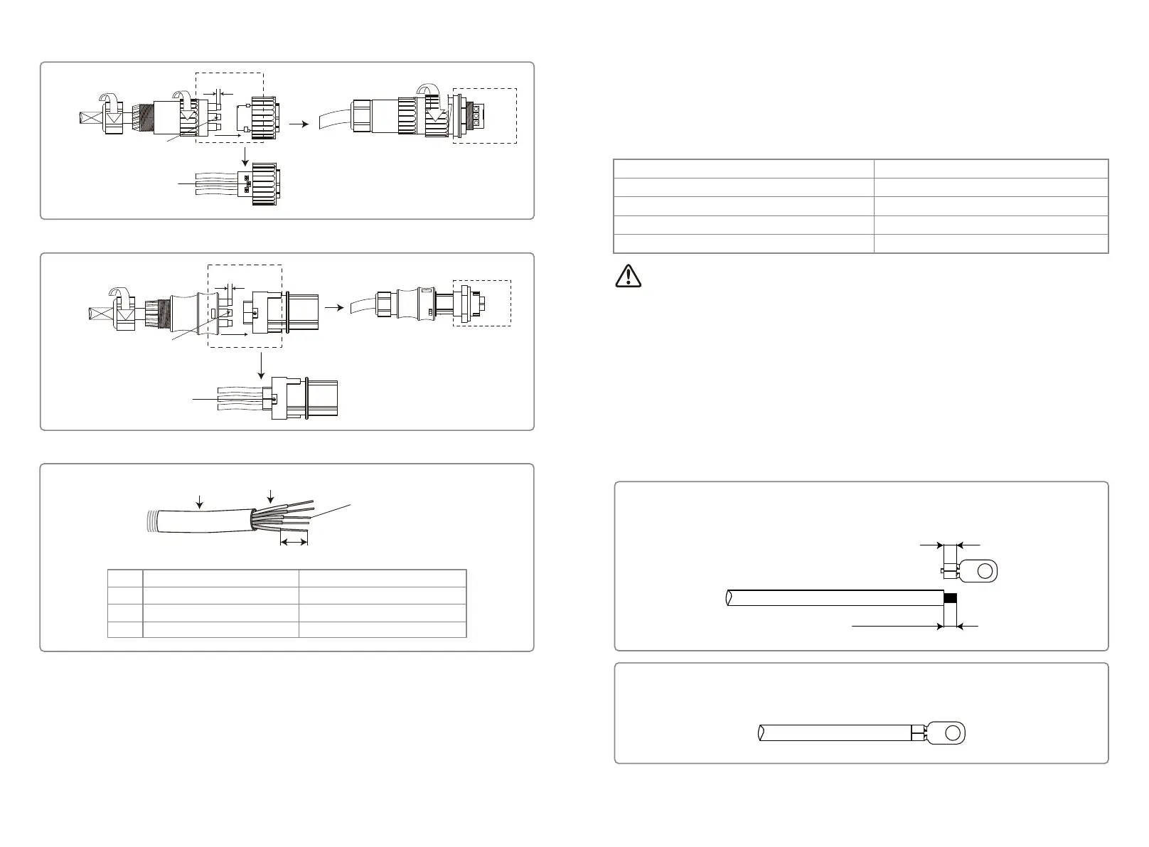
4.3.3 Earth Terminal Connection
The inverter is equipped with earth terminal according to the requirement of EN 50178.
All non-current carrying exposed metal parts of the equipment and other enclosures in the PV
power system must be grounded.
Please follow the steps below to connect "PE" cable to ground.
L1
L2 = L1 + (1~2mm)
Step 1
Strip the wire insulation sheet of a suitable length with a wire stripper.
Step 2
Insert the stripped wire into the terminal and compress it tightly by crimping pliers.
09 10
 Loading...