PRELIMINARY CHECKS
– Read the instructions in the manual carefully.
– Check that the gate is perfectly horizontal
– Check that it slides smoothly and without friction points
–
Check that there is an adequate base for fixing the motor, otherwise
prepare it
– Check that the electrical system complies with the characteristics
required
by the gearmotor
The gearmotor is delivered UNLOCKED
– Remove the motor from the box, check that it is not damaged. Unscrew
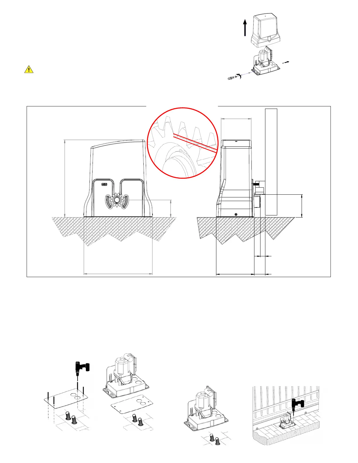
the screws A and B and remove the cover FIG.1
I
NSTALLATION
A = 105mm = VERTICAL DISTANCE BETWEEN THE TEETH OF
THE RACK AND THE GROUND
B = 20mm= HORIZONTAL DISTANCE BETWEEN THE DRIVE
WHEEL AND THE GATE
C = 55mm = HORIZONTAL DISTANCE BETWEEN THE BASE OF
THE MOTOR AND THE GATE
FOUNDATION PLATE (OPTIONAL)
If the base has yet to be prepared and the installation of the motor is
not immediate, it is possible to cement the foundation plate (NOT
INCLUDED) following the installation dimensions FIG.2
– Position the foundation plate as shown in FIG. 3
G
EARMOTOR POSITIONING
If there is a concrete base already prepared, it is possible to install the
motor, without using the foundation plate, following the installation
dimensions in FIG. 2. In this case, suitable M10 screw anchors must
be used
– Position the motor so that the cable outlets correspond to the
appropriate holes on the motor body. FIG. 4
– Secure the motor to the ground with suitable anchors, using the
slots provided FIG. 5.
Or if the foundation plate is installed, fix the motor to the 4 log bolts
provided as shown in FIG.3.
A
FIG. 3
C
FIG. 2
FIG.1
FIG.4
1,0mm
FIG.5
 Loading...