INSTALLING THE RACK
I
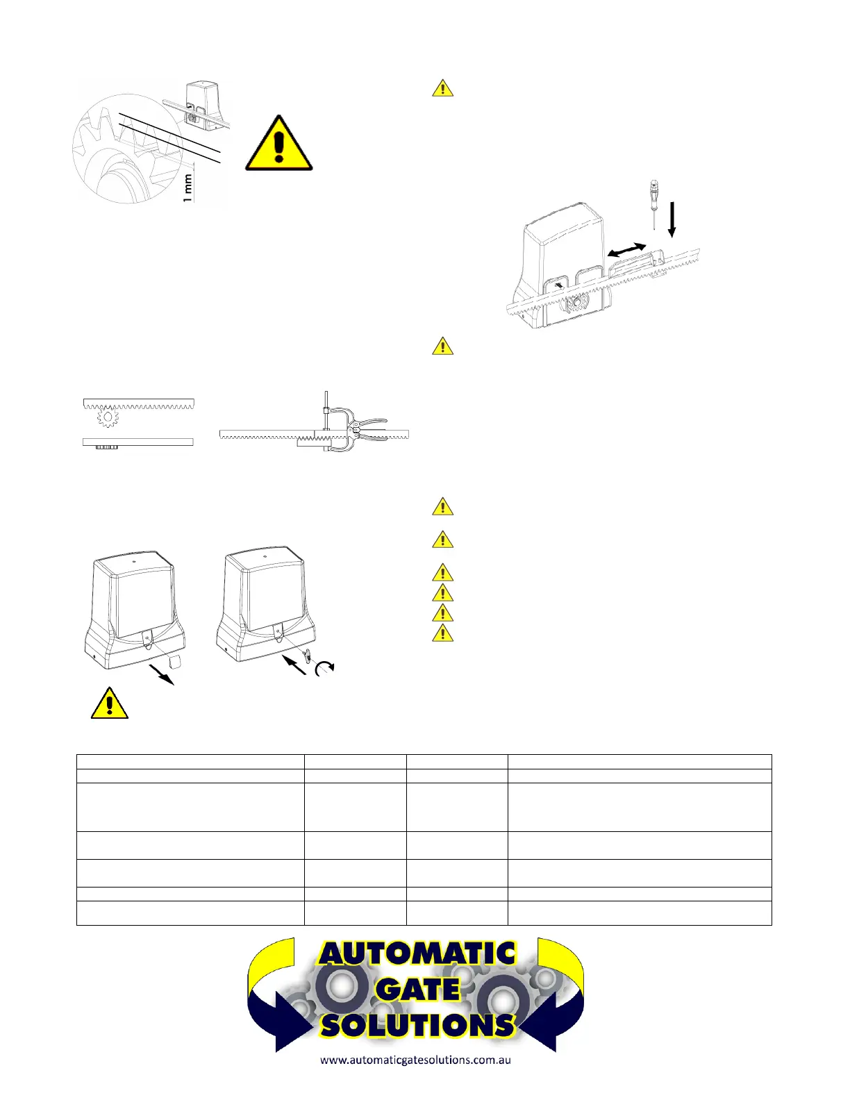
f the rack is already installed, check that there is a space of
approximately 1mm between the drive wheel and the rack FIG.5,
if the rack is not installed, proceed as follows:
–
Take the first piece of rack and position it on the motor sprocket
making sure that at the end of the installation there is always 1mm of
space (if necessary use temporary shims under the motor). Slide it to
the point indicated in FIG. 5
– Weld or screw the first pin or spacer to the gate (depending on the
type of rack).
– Apply all the other elements of the rack so that they are perfectly
joined and aligned with the first one. Use pliers and a piece of rack for
perfect alignment of one element with the other. See FIG. 6
EMERGENCY RELEASE
To
unlock the motor proceed as follows:
– remove the cap D
– Insert the supplied key E and turn CLOCKWISE for 4 turns FIG.7
– To overturn the motor turn ANTICLOCKWISE for 4 turns
FI
NAL OPERATIONS
Once the rack and motor have been fixed, release the motor see
FIG.8, and move the gate to check that it slides freely and effortlessly.
ATTENTION v
érifier qu'il ne "repose" pas sur la roue motrice du
moteur. Dans ce cas, réglez la crémaillère pour laisser environ 1 mm
d'espace entre le pignon du moteur et la crémaillère
– Install the limit switch cams on the rack FIG. 8 without fixing them in
a definitive way, in order to be able to adjust them in the optimal
position when programming the control unit.
CAUTION T
he limit switch cams are used to operate the limit
switches of the motor which, by means of the control unit, interrupt the
movement of the gate during opening and closing. They must be
positioned at the ends of the rack taking into account any inertia and
the delay in stopping the gate with respect to the operation of the limit
switches.
– Proceed with the electrical connections, program the control unit,
carry out the final test and reinstall the cover cards.
SCHEDULED MAINTENANCE WARNINGS
B
efore any maintenance operation, disconnect the power using
the main switch
T
he equipment must be maintained in such a way as to maintain
the conditions that guarantee safety and correct operation
A
lways use original spare parts
D
o not carry out any interventions that modify the machine
The modified machine needs a new CE mark
The adjustment of the function of the automation must be carried
o
ut by specialized personnel, in compliance with the relevant
regulations. During these operations the presence of two operators is
expected
SCHEDULED MAINTENANCE - OPERATIONS
DESCRIPTION FREQUENCY ENTRUSTED OPERATION
Photocells cleaning
Monthly Operator Clean with damp cloth
Control of the gate supports of the fall arrest
devices, the limit stops, the rack, the sliding
guide and the sliding of the gate
According to
necessity
Operator Check the integrity of all items, state of welds and
corrosion. Unhook the motor and check the friction
points of the gate and the distance between the
pinion and rack (1.0mm).
Control of the sensitivity of the electronic
clutch (torque regulation) of the control unit
Semiannual Technician Check the torque adjustment as indicated in the EN
12453 - EN 12445 standard
Control of the IP protection Semiannual Technician Check that there are no traces of moisture or water
inside the electrical enclosures
Monitoring current dispersion Annual
Technician Verify that the dispersion of current is less than 7.5 A
Control of signals Semiannual Operator Verify that the safety warning signage is complete
and intact
FIG. 5
FIG. 6
FIG.8
D
4
TURNS
CAUTION DO NOT RE-LOCK THE MOTOR WHILE
I
T‘S RUNNING
FIG.7
 Loading...