grace design m906
owner’s manual
10
grace design m906
owner’s manual
11
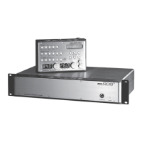
DC Power Cord
The rst connection to make is from the power supply unit to the main chassis with the supplied 6 pin
XLR DC power cord. Important: the DC power cable and the remote cable should be connected BEFORE
the AC power is turned on. This prevents incorrect power sequencing which can potentially cause damage
to the m906’s audio circuits.
AC Power Cord
Now connect the supplied AC cord to the power supply and then to an AC outlet with the supplied AC
cable. For safety, it is recommended that the cable be connected to a grounded outlet.
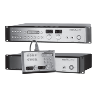
Connecting the Remote Control Unit to the Mainframe
The m906 remote control unit connects to the system mainframe via a supplied, high quality 25’ cable.
Each end of the cable terminates in a male DB15 connector. This cable provides RS-422 serial data,
power and headphone signal to the remote.
Make the connection by securing the remote cable to the remote control unit and then attaching the
other end to the mainframe. Both ends of the cable are identical so it doesn’t matter which end you
connect to the remote or mainframe. NOTE: The HD15 connector on each end of the remote cable does
not use a “VGA” computer monitor pinout (see the cable wiring diagram section of this manual). If you need
a cable longer than 25’, do NOT go to your local electronic supply store to purchase an off-the-shelf VGA
extension. It won’t work. Instead, please call us at 303-443-7454 and we’ll help you out.
Attaching the Tilt Adjustment Legs to the Remote Control Unit
The m906 remote control unit can be placed directly on a at surface or can be tilted forward with the
pair of supplied legs. If you intend to place the remote on a at surface, you should rst attach the self-
adhesive rubber feet (supplied) to each corner of the bottom of the chassis. This will prevent the unit
from scratching your surface and from the bottom panel of the remote from being scratched. The legs
for the remote are threaded on one end and screw into the threaded holes at the rear corners of the
bottom panel. The remote tilt angle can be adjusted slightly by screwing the legs in or out.
Power Sequence
Before powering up your m906, make sure your monitor speakers or power amps connected to your
monitors are turned OFF, which will prevent any “popping” in your speaker systems. Once the m906 and
the rest of your audio system are powered up, turn on the power to your speakers. When powering
down, we recommend that you rst power off your speaker system and then power down the m906.
It should also be noted that while the power sequence will not damage headphones connected to the
m906, you should NOT be wearing them when power is applied or turned off.
 Loading...