grace design m906
owner’s manual
6
grace design m906
owner’s manual
7
m906 remote control unit
channel
solo/mute
Left
Center Right
LS RS
Sub
input
5.1
AES3
5.1
ADAT
2ch
AES3
2ch
AES3
2ch
S/PDIF
2ch
ADAT/TOS
cue
5.1
BAL
5.1
UNBAL
2ch
BAL1
2ch
BAL2
1
2
talkback
input
GRACE DESIGN USA
main level / editheadphone level
calsel
dimmono mute
mon cue
(spkr 3)
spkr sel
analog
digital
solo/mute
A
B
C
F
G
E
H
D
L
J
I
N
M
P
K
O
R
Q
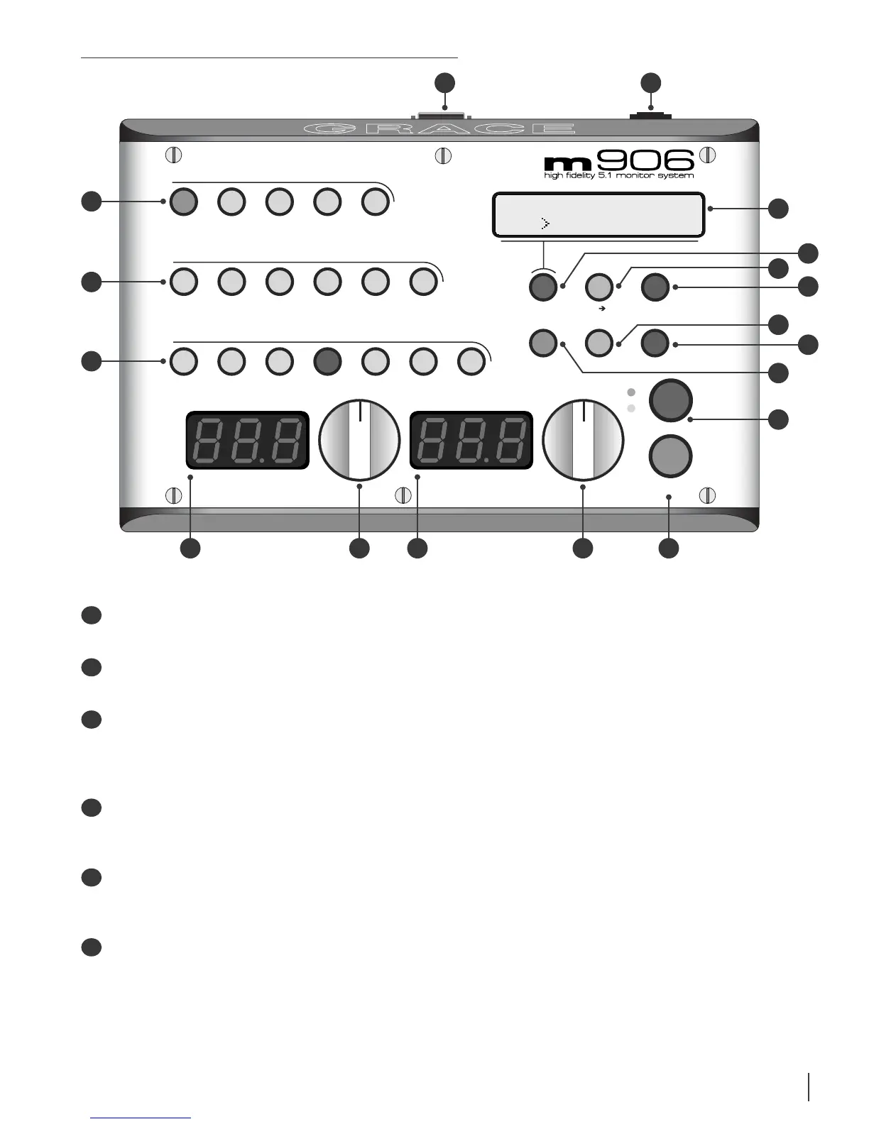
INPUT ANALOG SWITCHES This row of ve green LED illuminated switches is for selecting
between and monitoring any of the analog sources connected to the m906.
INPUT DIGITAL SWITCHES This row of six green LED illuminated switches is for selecting
between and monitoring any of the digital sources connected to the m906.
CHANNEL SOLO/MUTE SWITCHES These seven bi-colored switches are used to solo or mute
any individual channel being monitored by the m906. The rst six switches engage solo or
mute for the relevant channel, while the solo/mute switch is used to toggle between solo
or mute mode.
HEADPHONE LEVEL DISPLAY This blue, 3 digit headphone level display shows the current
relative headphone output level value based on the position of the headphone level rotary
encoder. The range of this display is 0 to 100dB.
HEADPHONE LEVEL ROTARY ENCODER This stepped rotary encoder controls the headphone
output level in .5dB increments. When monitoring multichannel sources, pushing this
encoder knob alows the headphone source channels to be selected.
MAIN LEVEL/EDIT DISPLAY This blue, 3 digit main level/edit display shows the current
relative main speaker output level values based on the position of the main level rotary
encoder. The range of this display is 0 to 100dB. The display also shows edit values when
the system is in CAL mode. (contunued)
A
C
B
F
D
E