Maintenance
Pressure Relief Procedure
INJECTION
HAZARD
T
o reduce the risk of serious injury
,
including fluid injection, splashing in the
eyes or on the skin, or injury from mov
-
ing parts, always follow this procedure whenever
you shut of
f the pump, and before inspecting,
removing, cleaning or repairing any part of the
pump or system.
WARNING
1.
Close the supply pump’
s bleed-type master air
valve (required in pneumatic systems).
2.
Open the dispensing valve until pressure is fully
relieved.
3.
Open the fluid drain valve at the pump fluid outlet.
Leave the drain valve open until you are ready to
use the system again.
If you suspect that the dispensing valve, extension, or
grease fitting coupler is clogged, or that pressure has
not been fully relieved after you have followed the
steps above, very slowly
loosen the coupler or hose
end coupling to relieve the pressure gradually
, then
loosen it completely
. Then clear the clog.
Replacing the Service Hose
1. Relieve
the pressure
.
INJECTION HAZARD
T
o reduce the risk of serious injury
whenever you are instructed to relieve
pressure, always follow the
Pressure
Relief Procedure
above.
WARNING
2.
Fully extend the hose and latch it.
3.
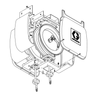
Attach a C-clamp (G) to the reel flange to help
prevent the reel from unintentionally becoming
unlatched and spinning freely
. See Fig. 1
1.
Never
allow the reel to spin freely
. Doing so causes
the hose to spin out of control, which could cause
serious injury if you are hit by the hose.
WARNING
4.
Disconnect and remove the service hose.
5.
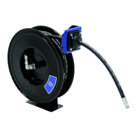
Attach the hose (48) to the hose reel swivel (34),
and carefully remove the C-clamp. See Fig. 12.
6.
Pull the hose hard enough to release the latch,
and slowly allow the hose to retract.
7.
Position the hose stop so the hose extends far
enough for all operators to reach the dispensing
valve.
Fig. 11
36
37
G
03724A
Fig. 12
34
48
03722
 Loading...