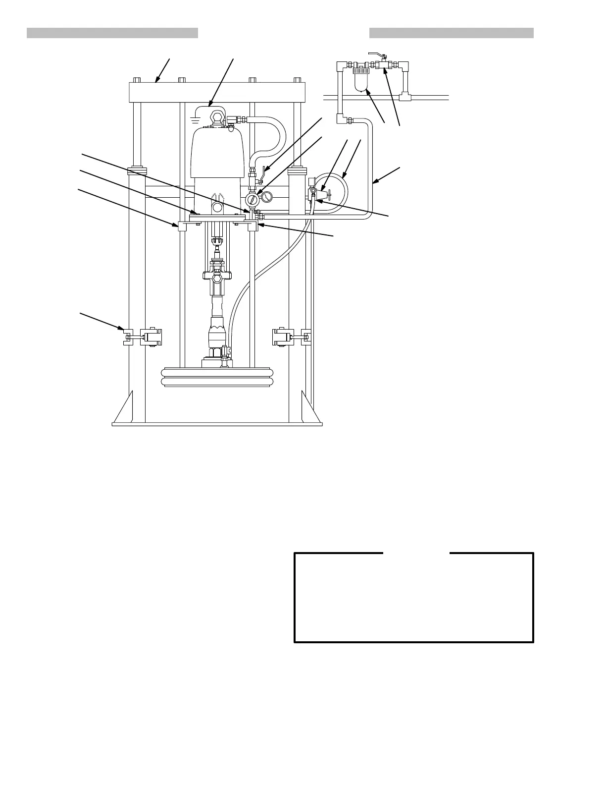
TYPICAL INSTALLATION
KEY
A Air
Line Filter
B Bleed–T
ype Master Air V
alve
(required, for pump)
C
Pump Air Regulator
D
Air Manifold
E
Air Supply Hose (for ram)
F
Ram Air Regulator
G Bleed–T
ype Master Air V
alve
(for accessories)
H
Main Air Supply Line
J
Drum Clamps
Y
Ground Wire (required)
3
Support Beam
4 Ram Director Valve
26, 27
Pump Mounting Hardware
35 Mounting Bracket Setscrews
57
Pump Mounting Brackets
66
Air Manifold Mounting Bracket
A
D
EFG
H
Y
J
B
C
57,
35
3
4
26, 27
66
This
air–powered ram extruder forces high viscosity flu
-
ids
into the intake valve of the fluid pump. Wiper rings
and
other accessory equipment for use with this ram are
listed
in the ACCESSORIES section.
NOTE: To convert the ram from air to hydraulic opera-
tion, install piston kit 220–501 (see page 18).
Contact
your Graco representative for details.
Locating the Ram
NOTE: Refer
to the Dimensional Drawing on page 19
for
ram
mounting and clearance dimensions.
1. Select a convenient location for the equipment.
Check
that there is suf
ficient overhead clearance
for
the pump and ram when the ram is
in
the fully raised
position. Make sure the air regulators for the pump
and
ram are fully accessible.
2.
Level the base of the ram, using metal shims.
3. Using
the holes in the base as a guide, drill holes for
1/2
in. (13 mm) anchors. Bolt the ram to
the floor with
anchors which are long enough to prevent the unit
from tipping. Refer to the Dimensional Drawing on
page
19.
4. Mount
the pump on the ram, following the applicable
procedure
on page 5 or 6.
Installing Accessories and Connecting Air
Lines
1. Install
an air line filter (A) on the air supply line to re
-
move harmful moisture and contaminants from the
compressed
air supply
.
2. Install
a bleed–type master air valve (B)
downstream
from
the pump air regulator (C).
WARNING
The
bleed–type master air valve (B)
is required in
your system to relieve air trapped between this
valve
and the pump after the pump air regulator is
closed. Trapped air can cause the pump to cycle
unexpectedly,
which could result in serious bodily
injury,
including splashing in the eyes or on the
skin
and
injury from moving parts.
3. Install an air manifold (D) on the mounting bracket
(66).
Connect a suitable air hose (E)
between an out
-
let
port of the air manifold
and the air inlet of the ram
air regulator (F).
4. Install a second bleed–valve (G) upstream from all
accessories,
to isolate the
accessories for servicing.
Connect
the main air supply line (H) to the manifold
(D).