306-934ą5
INSTALLATION
Mounting the Pump (Model 207–279 Ram)
NOTE: The
Pump Selection Chart on page
3 lists pumps
commonly
mounted on this
ram. Installing other
pumps on the ram may require alternate parts,
which are packed in separate plastic bags. For
information, contact your Graco representative
or Graco Technical Assistance at
1–800–543–0339.
Mount
the pump as follows. Refer to the T
ypical Installa
-
tion
on page 4.
1. Remove
the mounting plate (58); it is not required
for
those pumps listed in the chart on page 3. Position
the mounting brackets (57) so that the top of the
pump
will clear the support beam (3). Set the pump
on the mounting brackets (57) with the air inlet
toward
the ram director valve (4). Attach the pump to
the mounting brackets with the screws (27) and
washers
(26) provided.
2. Remove the four screws (25) and washers (31)
holding
the standard seal plates (62) to the ram
plate
(63)
and remove the top seal plate (62) and seal (56).
Leave the bottom seal plate (62) and gasket (61) in
place.
See Fig 1.
3.
For
15:1 and 25:1 ratio Senator
, 25:1 and 40:1
ratio
Bulldog, and 55:1 ratio King standard extrusion
pumps,
slide the top seal plate (62) up over the pump
intake valve and push the seal (56) onto the pump
intake
housing. Then continue with step 4.
For
10:1 ratio Bulldog and 20:1 ratio
King pumps with
a flanged intake housing,
discard the top seal plate
(62) and seal (56). Remove and discard the bottom
seal plate (62). Align the holes in the intake valve
flange with those in the gasket (61) and ram plate
(63).
Then continue with step 4.
4. Loosen the mounting bracket setscrews (35), and
carefully
lower the pump until the intake valve is
be
-
low
the gasket (61), then tighten the setscrews.
5.
If applicable for your installation,
push the seal (56)
down
firmly against the bottom seal plate (62).
6. Align the holes in the top seal plate or pump intake
flange
(as applicable)
with the holes in the ram plate
(63). Secure tightly to the ram plate with the four
screws
(25) and washers (31).
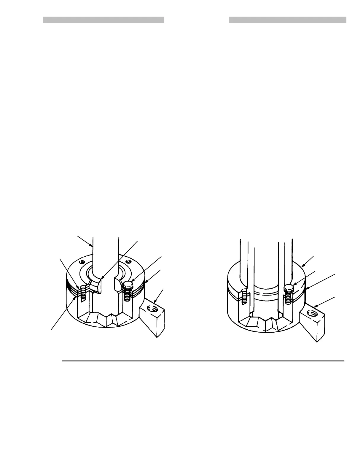
Fig 1
63
61
INTAKE
HOUSING
FLANGE
63
61
25, 31
25, 31
56
62
62
10:1 BULLDOG AND 20:1 KING PUMPS,
WITH FLANGED INT
AKE HOUSING
ST
ANDARD EXTRUSION
PUMPS
PUMP
INT
AKE
HOUSING