12 824191
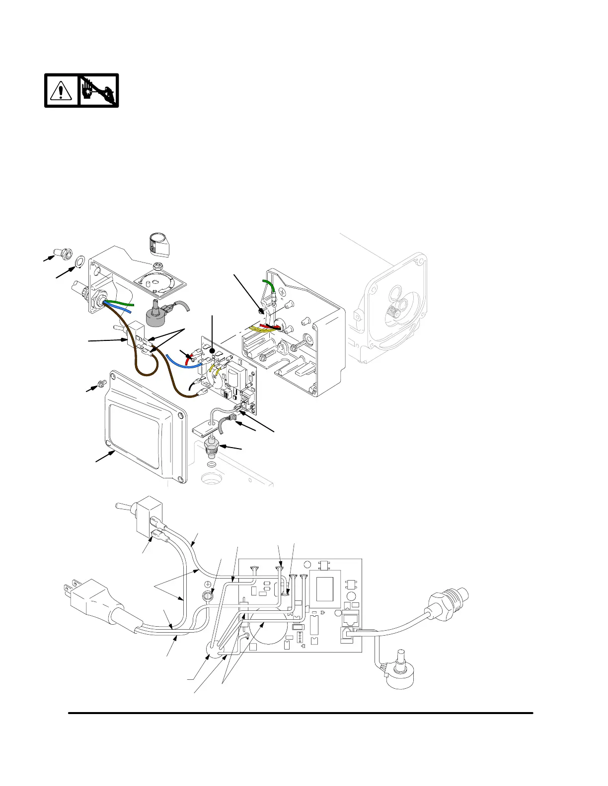
On/Off Switch Replacement
Removal
1.
Relieve pressure; page 4.
2. Fig. 7. Remove four screws (18) and pressure
control cover (39).
3. Disconnect two wires (A) from ON/OFF
switch (23).
4. Remove toggle boot (25) and locking ring (24).
Remove ON/OFF switch (23).
Installation
1. Install new ON/OFF switch (23). Install locking ring
(24) and toggle boot (25).
2. Connect two wires (A) to ON/OFF switch.
3. Install pressure control cover (39) with four
screws (18).
9580A
Fig. 7
39
A
18
23
36
52
E
D
35
36
25
24
37
ON/OFF
Switch
Power
Plug
Potentiometer
from Motor
Red (+)
Yellow
White
Black
Green
Black (–)
Pressure
Transducer
Ref 60
Ref 23
Ref 29
Ref 26
Ref 52
Ref 34
9535A
Wiring Diagram
TP1
L2 L1