3106942
Installation and Operation
Installation
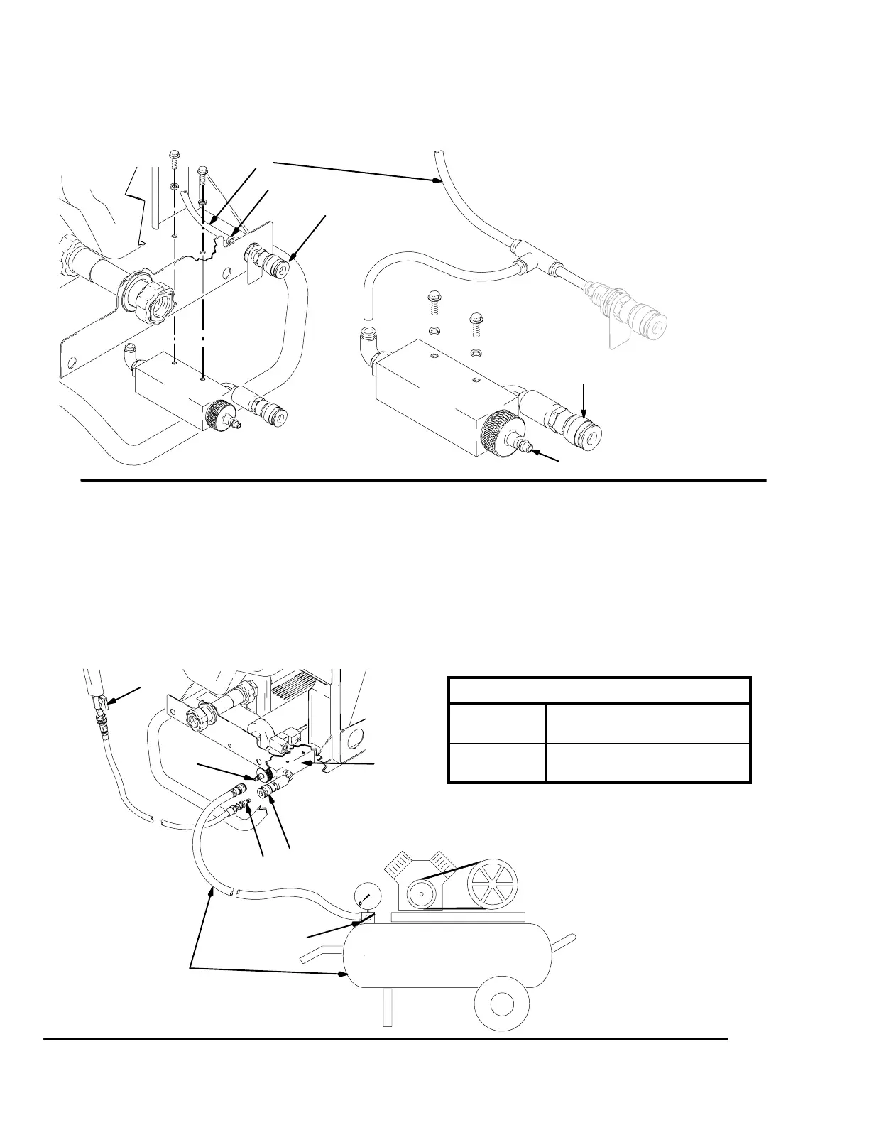
Fig. 1. Remove hopper and front shroud. Install valve. Push in on fitting ring (A) and disconnect air line (B).
Cut off 2 in. of air line (B). Connect air lines. Install front shroud and hopper.
Fig. 1
B
A
J
ti4961b
D
F
ti4960b
Operation
Air connection (J), shown in Fig. 1, is not used in this
configuration.
1. Fig. 2. Connect external air supply (C) to valve male
air fitting (D).
2. Connect spray gun air line (E) to valve (F).
3. Open spray gun air valve (G) all the way.
4. Pull spray gun trigger and adjust air flow with air
pressure regulator (H) (not supplied by Graco) on
external air supply
5. Use spray gun air valve (G) for fine adjustment.
Air Flow (cfm) Operating Range at gun
Connection J 1 – 6 cfm
(no additional air required)
Connection F 5 – 20 cfm
(requires external air supply)
Fig. 2
ti4962b
Air
Vent
D
G
E
F
H
C