4 306–667
Installation
General
WARNING
INJECTION HAZARD
T
o reduce the risk of serious injury whenever you
are instructed to relieve the pressure, always follow
the
Pressure Relief Procedure
on page 5.
NOTE:
Numbers and letters in parentheses in the text
refer to reference numbers in the Figures and Parts
Drawing.
WARNING
INJECTION HAZARD
B
e s
ur
e y
our syste
m h
a
s a b
leed-typ
e m
aster air
valve
(
pneumati
c v
alve
s o
nly
) a
n
d a f
lui
d d
rain
v
alve.
These
t
w
o a
ccessorie
s h
elp reduc
e t
he ris
k o
r
serious
i
njury
, i
ncluding
f
lui
d i
njection
, s
plashin
g i
n t
he
eyes
o
r o
n
t
h
e s
kin
, o
r i
njur
y f
ro
m m
ovin
g p
art
s i
f y
ou
are
a
djustin
g o
r repairin
g t
h
e p
um
p o
r gun.
The bleed-type master air valve relieves air
trapped between this valve and the pump after
the air regulator is shut of
f. T
rapped air can
cause the pump to cycle unexpectedly
.
The fluid drain valve assists in relieving fluid
pressure in the displacement pump, hose, and
gun; triggering the gun to relieve pressure may
not be suf
ficient.
1.
Connect a grounded fluid hose to the gun inlet.
2.
With no tip installed, start the pump/sprayer
. Flush
it according to the instructions supplied with it.
Prime the system with the fluid you are using.
3.
Relieve the pressure.
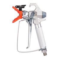
4.
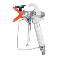
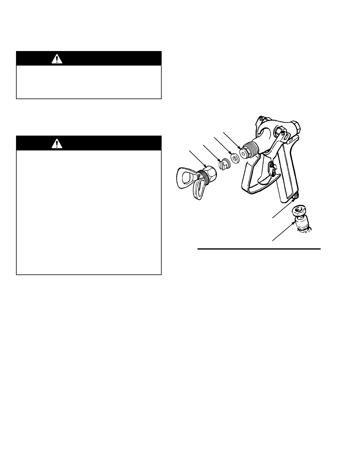
With the gun safety latch engaged, unscrew the tip
guard (25) and install the tip (B) and gasket (17) in
the nut of the tip guard. Screw the assembly firmly
onto the gun. T
ighten with a wrench. See Fig. 1.
Fig. 1
25
B
17
23
D
E
NOTE:
Failure to install the tip gasket (17) will result in
leaking.
5.
Strain the fluid you are spraying if it contains
particles which could clog the spray tip.