13309255
On/Off Switch Replacement
695/795 120 Vac (825000, 825002, 825005, 825020, 825022, 826024, 826025)
Removal
1.
Relieve pressure; page 4.
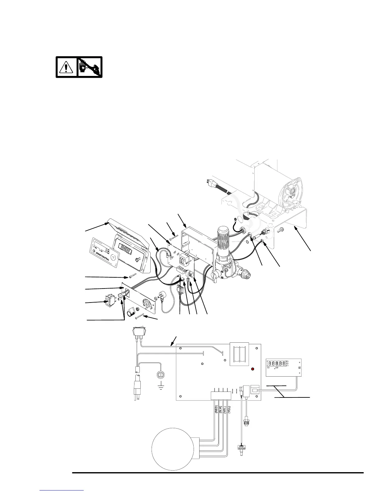
2. Fig. 10. Remove four screws (60) and pressure
control cover (49). Disconnect display connector
(B) (not available on all sprayers).
3. Remove two screws (108) and control panel (67).
4. Disconnect two wires (A) from ON/OFF
switch (86).
5. Squeeze inside tabs on ON/OFF switch (86) and
remove from control panel (67).
Installation
1. Push ON/OFF switch (86) into control panel (67)
until inside tabs snap in place.
2. Connect two wires (A) to ON/OFF switch (86).
3. Install control panel (67) with two screws (108).
4. Connect display connector (B) (not available on all
sprayers). Install pressure control cover (49) with
four screws (60).
Wiring Diagram
ti0949A
Pressure
Transducer
Ref 68
Potentiometer
Ref 64
Red (+)
Black (–)
Yellow
Power Cord
Ref 66
On/Off
Switch
Ref 86
Black
White
70
Display
Green
Motor
Fig. 10
49
60
86
A
67
695/795 120 VAC
112
41
Black
D EBC
108
42
72
58
108
43
Ref
38
LED
Not available
on all sprayers