20 309255
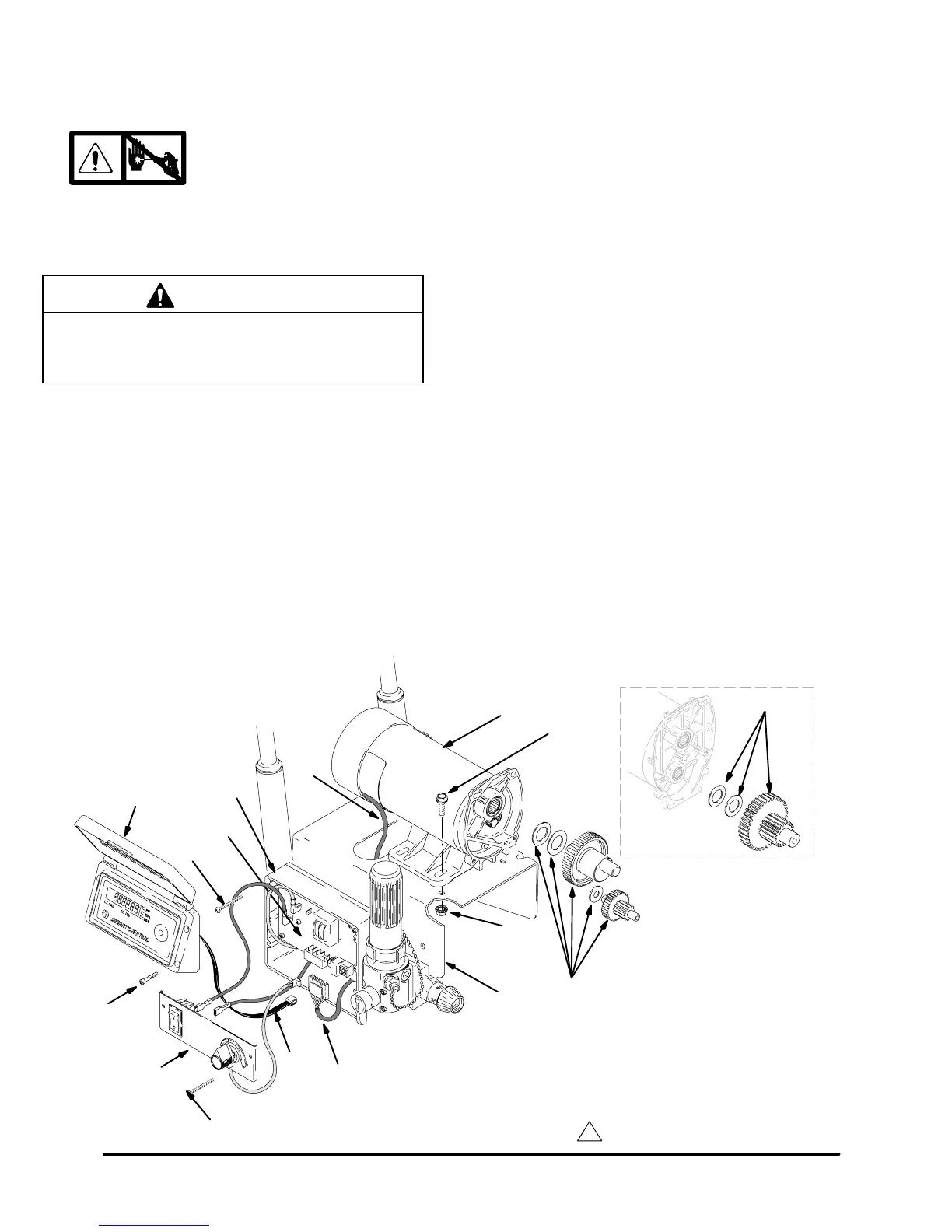
Motor Replacement
Removal
1.
Relieve pressure; page 4.
2. Remove pump (79); Displacement Pump Re-
placement, page 21.
CAUTION
Do not drop gear cluster (A) when removing drive
housing (78). Gear cluster may stay engaged in
motor front end bell or drive housing.
3. Remove drive housing (78); Drive Housing Re-
placement, page 19.
4. Remove four screws (60) and cover (49).
5. Disconnect lead (B) from board (112).
6. Remove two screws (108) and panel (67).
7. Remove two top screws (108) and housing (58).
8. Disconnect all leads from board (112).
9. Remove strain relief (43, page 13, 14).
10. Thread motor lead (J) out through slot in frame.
11. Remove four screws (31), nuts (127) and motor
(75) from frame (72).
Installation
1. Install new motor (75) on cart frame (72) with four
screws (31) and nuts (127).
2. Thread motor lead (J) in through slot in frame.
3. Install strain relief (43, page 12, 13, 14).
4. Connect all leads to board (112).
5. Install control housing (58) with two screws (108).
6. Install panel (67) with two screws (108).
7. Connect lead (B) to board (112).
8. Install cover (49) with four screws (60).
9. Install drive housing (78); Drive Housing Re-
placement, page 19.
10. Install pump (79); Displacement Pump Replace-
ment, page 21.
Fig. 15
1
Liberally apply grease
108
60
67
49
B
31
72
127
J
(A) 695
(A) 795,1095
112
J
108
75
58
ti0948A