15309255
Pressure Control Repair
Motor Control Board
Removal
Refer to Fig. 10 or 11 depending on sprayer and
voltage.
1.
Relieve pressure; page 4.
2. Remove four screws (60) and pressure control
cover (49). Disconnect display connector (B).
3. Remove two screws (108) and control panel (67).
4. Disconnect at motor control board (112):
Motor connector: two yellow, black (+) and
red (–).
Lead (D) from potentiometer.
Lead (E) from transducer.
Wires from power cord and switch
5. Remove six screws (41) and motor control
board (112).
Installation
1. Clean pad on rear of motor control board. Apply
small amount of thermal compound 073019 to pad.
2. Fig. 10. Install motor control board (112) with six
screws (41).
3. Connect to motor control board (112):
Lead (E) to transducer.
Lead (D) to potentiometer.
Motor connector: two yellow, black (+) and
red (–).
Wires to power cord and switch
4. Route loose wires so none lay in contact with
inductor coil on filter board (not 120 Vac sprayers).
See Wiring Diagram CAUTION, Fig. 11.
5. Install control panel (67) with two screws (108).
6. Install display connector (B). Install pressure
control cover (49) with four screws (60).
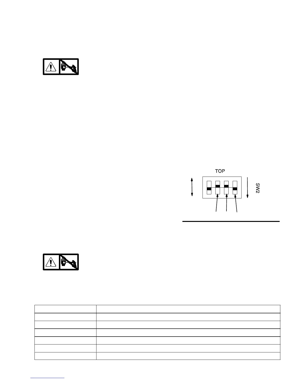
Digital Display Settings (Not available on all
sprayers)
The units on the digital display may be set to psi, bar,
MPa and gallons or liters.
1. Fig. 10. Remove four screws (60) and cover (49).
Disconnect display cable (B).
2. Set switches as desired, Fig. 12.
Fig. 12
MPa bar
liters
gallons
psi
SET
Shown set for
gallons and psi
Stored Data (Not available on all sprayers)
The SmartControl contains stored data to assist with troubleshooting and maintenance. To view this stored data on
the digital display, proceed as follows:
1.
Relieve pressure; page 4.
2. Plug in sprayer.
3. Hold down display button and turn sprayer ON.
4. Release display button about 1 second after
turning on sprayer.
Sprayer model number displays (U695, U795, etc.) for
a few seconds and then data point 1 is displayed.
5. Push display button and next data point displays.
6. Turn sprayer OFF and then ON to leave stored
data mode.
Data Point Definition
1 Number of hours power switch has been ON with power applied
2 Number or hours motor has been running
3 Number of hours sprayer has been above 500 psi with power applied
4 Total gallons pumped with pressure above 1000 psi
5 Last recorded Error Code E=XX. See Error Code messages on page NO TAG.
6 Control board software revision number