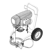
Fig 9
LEATHER PACKINGS
LIPS OF V-PACKINGS
IN THROAT MUST
FACE DOWN
tN PISTON MUST
lbs face down r 1
!
212”
218”
PLASTIC
PACKINGS
217*
PLASTIC
PACKINGS
Fig IO
Disassembling the Pump
(Refer to Figures 9 and IO.)
1. Unscrew the intake valve (222) from the cylinder
(216). Remove the gasket (2061, ball guide (2151,
stop pin (207) and ball (204) from the valve. Clean
and inspect the parts for wear or damage, replacing
parts as needed. Always use a new gasket (includ-
ed in Repair Kit 218-033).
2. Unscrew and remove the packing nut (221) and
plug (201).
3. Use a plastic mallet to tap the piston rod
down,
then pull the rod out through the bottom of the
cylinder.
4.
Remove the throat packings (209, 218) and glands
(211, 212).
5.
Clamp the flats of the piston rod in a vise. Use a
7/8 in. wrench to loosen the retaining nut (214).
Then use the wrench to unscrew the piston valve
(224) from the rod.
6. Remove the backup washer (219). wiper (2051,
packings (208, 217) and glands (213, 220).
Reassembling the Pump
Assembly Notes:
(1) Use Repair Kit No. 218-033 to repair the displace-
ment pump. Reference number in parentheses with
an asterisk, for exampe, (210*), show the parts in-
cluded in the kit. Use all the new parts, even if the
old ones still look good as the old parts cause the
new ones to wear prematurely.
(2)
Alternate leather and plastic packings as shown in
Fig 3. Notice that the lips of the throat “V” pack-
ings face
down,
against pressure, and the lips of
the piston “V” packings
face up,
against pressure.
The lips of the U-cup wiper (205),
face down.
Incor-
rect installation damages the packings and results
in the pump leaking.
(3)
1.
2.
3.
4.
5.
Coat the piston rod, inside of the cylinder and the
packings with a lightweight oil to help prevent
packing damage when inserting the piston rod.
Check the outside of the piston rod (223) and the in-
side of the cylinder (216) for scoring or scratches. If
the parts are damaged, new packings will not seal
properly. Replace these parts if needed.
Stack the backup washer (219*), wiper (205*),
female gland E?O*), packings f217*, 208”) and
male gland (213”) onto the piston valve. See
Figures 11 & 12.
Tighten the packing retaining nut (214) onto the
piston valve (224) and torque to 3 to 4 in-lb 10.34 to
0.35 N-m)-about finger tight.
Use a pen to make a light mark on the packings
where they align with one of the flats on the nut.
See Fig 11.
Place ball (203) on piston valve (224). Apply
one
drop
of thread locking compound on threads of
valve. Then hand tighten the valve assembly into
the piston rod just until the nut meets the face of
the rod. See Fig 12.
16
307643
 Loading...