10 309941
Pressure Control Repair
100 – 120 Vac North American and Japan/Taiwan Motor Control Board
Removal
1.
Relieve pressure; page 5.
Wait 5 minutes before servicing.
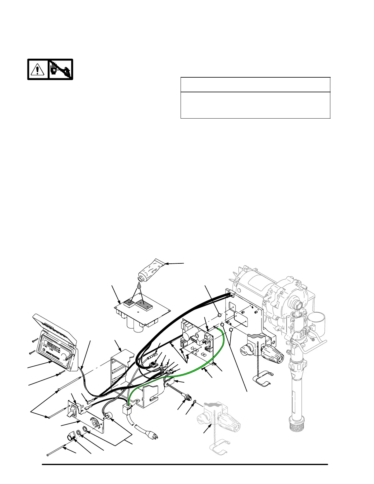
2. Fig. 3. Remove four screws (38) and cover (96).
3. Disconnect display connector (A) from motor
control board (95).
4. Remove bottom two screws (39) and allow control
panel (68) to hang down freely.
5. Disconnect control board power lead(s) (D) from
ON/OFF switch (33) and motor control board (95).
6. Disconnect potentiometer connector (C) from
motor control board.
7. Disconnect transducer connector (E) from motor
control board.
8. Disconnect motor connectors (F, G and H) from
motor control board.
9. Remove top two screws (39) and control box (61).
10. Remove five screws (27), three screws (102) and
motor control board.
Installation
1. Fig. 3. Apply small amount of thermal compound
110009 (5) to shaded component areas on rear of
motor control board (95).
CAUTION
To reduce risk of motor control board failure, do not
overtighten screws (102) which can damage the
electric components.
2. Install motor control board (95) with five screws
(27). Torque to 9–11 in-lb (1.02 – 1.24 N·m). Install
and torque three screws (102) to values shown in
Fig 3.
3. Connect motor connectors (F, G and H) to motor
control board.
4. Install control box (61) with top two screws (39).
5. Connect transducer connector (E) to motor control
board.
6. Connect motor control board power lead(s) (D) to
ON/OFF switch (33).
7. Connect potentiometer connector (C) to motor
control board.
8. Install control panel (68) with two screws (39) .
9. Connect display connector (A) to motor control
board (95).
10. Install cover (96) with four screws (38).
Fig. 3
100 – 120 Vac
North American
and Japan/Taiwan
39
38
96
68
ti4289a
33
F
G
H
102
95
61
A
26
27
5
95
80
20
40
67
E
A
C
82
115
34
39
Tighten 2 screws
to 7–10 in–lb
Tighten 1 screw
to 14–17 in–lb
D
D
 Loading...