Repair manual GRAMMER seat suspension MSG95EAC – November 2012
Material no. 1 277 338
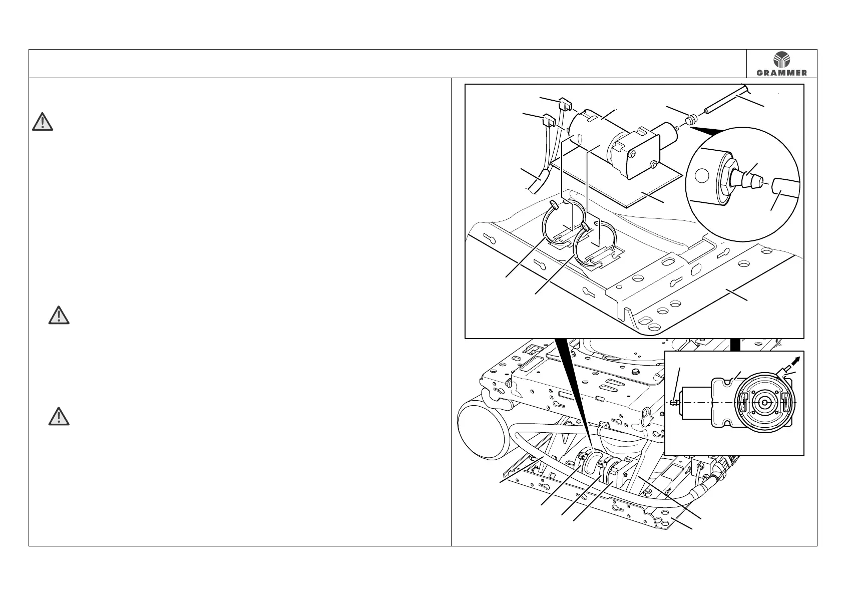
3.8 Compressor – removal and installation
Page 1 of 2
Removal and installation
ATTENTION Leak test!
Perform a hydrostatic test of the seat
suspension upon installation of the
compressor (1). To do this, apply a 60 kg
load to the seat suspension for 24 hours.
The lowering within this time must not
exceed 15 mm.
1 Remove the seat (see Chapter 3.1).
2 Remove the bellows at the lower
suspension part (see Chapter 3.3),
push it upwards and fix it in this
position.
3 WARNING Risk of crushing!
Move the seat suspension to the
highest position and secure at the back
between the swinging structure and the
lower suspension part by means of
suitable spacers.
4 WARNING The pressure in the
pneumatic system may cause injury!
Vent the pneumatic system before
removing the compressor (1).
5 Mark and remove two right-angle plugs
(8).
Installation notes:
• Reconnect the electrical connection
according to the marking.
• When establishing the electrical
connection, the cable output of the
compressor cable (7) at the right-angle
plug (8) must point downwards.
6 Mark the points where the compressor
(1) is secured to the lower suspension
part (5) with two cable ties (6) and
remove the cable ties (6).
Installation notes:
• Run the cable ties (6) through the
corresponding cut-outs in the lower
part of the suspension (5) in such a
way that the locking head of the cable
ties (6) points forwards (arrow).
• Loosely close the cable ties (6) in
such a way that the compressor (1)
can still be moved.
• Align the compressor (1) so a
collision with the swinging structure (9)
is avoided and then use pliers to
tighten the locking head of the cable
ties (6) to 360 ± 30 N in the tensile
direction.
2864
1
8
6
6
4
7
5
8
2
3
3
1
2
1
6
1
5
6
6
7
9
1
10
10