24
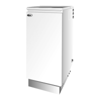
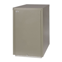
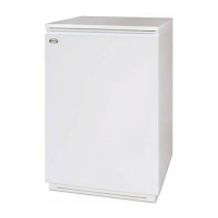
Grant Vortex Indoor/Utility, System and Boiler House Oil Boilers
Fig. 13 - Sealed system
4 - GENERAL BOILER INFORMATION
50/90 Boiler House
Flow connection: A 1" BSP socket is provided on the
boiler for the flow connection. This is located
underneath the side blanking plate on the right hand
side panel. The flow pipe will need to be vented, as it
is the highest point on the primary heat exchanger.
Return connection: A 1" BSP socket is located on
top of the boiler. This return pipe will also need to be
vented at some point, as it is the highest point on the
secondary heat exchanger.
90/120, 120/155 Boiler House
Flow connection: A 1" BSP socket is provided for the
flow connection. This is located on the right hand side
of the boiler. This flow pipe will need to be vented, as
it is the highest point on the primary heat exchanger.
Return connection: A 1" BSP socket is located on
top of the boiler. This return pipe will also need to be
vented at some point, as it is the highest point on the
secondary heat exchanger.
155/200, 200/240 Boiler House
Flow connection: A 1¼" BSP socket is provided for the
flow connection. This is located on the right hand side of
the boiler. This flow pipe will need to be vented, as it is
the highest point on the primary heat exchanger.
Return connection: A 1¼" BSP socket is located on
top of the boiler. This return pipe will also need to be
vented at some point, as it is the highest point on the
secondary heat exchanger.
Sealed systems
4.14
See Fig. 13
1 All Grant Vortex boilers are suitable for use with
sealed systems complying with the requirements of
BS 5449.
The maximum temperature of the central heating
water is 75° C.
2 The system must be provided with the following items:-
a Diaphragm expansion vessel complying with
BS 4814.
b Pressure gauge.
c Safety valve.
d Approved method for filling the system.
Refer to BS 7074:1 for further guidance.
3 The expansion vessel can be fitted in either the
return or flow pipework in any of the
recommended positions as shown in Fig. 13. To
reduce the operating temperature of the expansion
vessel diaphragm, position it below the pipe to
which it is connected. The expansion vessel may be
positioned away from the system, providing the
connecting pipe is not less than 13 mm diameter.
4 The pressure gauge should have an operating range
of 0 to 4 bar.
5 The safety valve, set to operate at 2.5 bar, should
be fitted in the flow pipework near to the boiler.
The pipework between the safety valve and boiler
must be unrestricted, i.e. no valves. The safety
valve should be connected to a discharge pipe
which will allow the discharge to be seen, but
cannot cause injury to persons or property.
Water connections - Boiler House models
4.13
 Loading...
