30
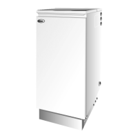
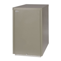
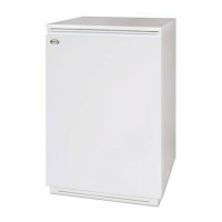
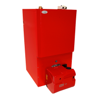
Grant Vortex Indoor/Utility, System and Boiler House Oil Boilers
Indoor/Utility and System models:
1 Carefully remove the packaging from the boiler
and remove it from the transit pallet.
2 Pull the front panel forward at the top to disengage
the fixing clips then lift it up and off the boiler.
Remove the literature packs.
3 Lift off the case top panel(s) and remove the water
connecting fittngs.
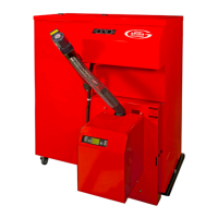
Boiler House models:
1 The Boiler House boiler comes in two separate
cartons, one containing the boiler and the other
containing the burner and drain trap. (50/90 - the
dual thermostat is also included).
2 Carefully remove the packaging from the boiler
and unpack the carton containing the remaining
items.
3 Remove the literature pack from the combustion
chamber of the boiler through the front burner
opening.
Unpack the boiler
6.1
Prepare the wall
6.2
6 - BOILER INSTALLATION
See Fig. 19 and 19a
If the boiler is to be used with a low level balanced
flue (Yellow system) make the hole in the wall for the
flue as shown in Fig. 19.
Note: Dimension B given in Fig. 19a includes an
extra 10 mm over the size of the terminal to provide
clearance for fitting.
Fig. 19a - Low level balanced flue (Yellow System)
Fig. 19 - Low level balanced flue
Side wall
Rear wall
Note: This dimension is given with
the boiler pushed back against
the rear wall. Any clearances
must be added to it.
Hole to be
cut in wall
Boiler
centre line
Outline
of boiler
Rear exit
Side exit
C
C
A
A
B
50/70 Indoor/Utility, 50/90 Indoor/Utility, System and Boiler House
90/120, 120/155 Indoor/Utility, System and Boiler House
155/200, 200/240 Indoor/Utility and Boiler House
C
768
780
1102
Dimension (mm)
Model
A dia
127
162
162
B
115
115
112
 Loading...
