Combi V3, Combi Max and Vortex Combi models
48
11 - BOILER COMPONENTS
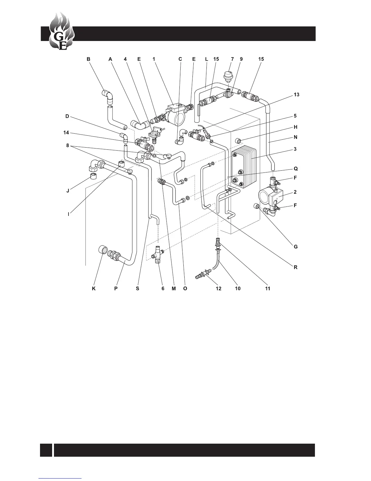
Fig. 33a - Vortex Combi components/connections
Main Components
1 Circulating pump - heating
2 Circulating pump - hot water (primary store)
3 Plate heat exchanger
4 Pressure switch
5 Flow switch
6 Thermostatic mixing valve
7 Automatic air vent
8 Manual air vent (x 2)
9 Pressure relief valve
10 Filling hose
11 Filling loop - cold inler isolating valve
12 Filling loop - heating system isolating valve
13 Isolating valve - cold inlet
14 Isolating valve - heating return
15 Non return valve (x 2)
Connections/pipe
A Heating system flow - push-fit elbow
B Heating system return - push-fit elbow
C Cold water inlet - push-fit elbow
D Hot water outlet - push-fit elbow
E Pump isolating valves - heating pump
F Pump isolating valves - hot water (store) pump
G Primary inlet to store
H Primary outlet from store
I Primary inlet to condensing heat exchanger
J Primary outlet from condensing heat exchanger
K Primary return to main heat exchanger
L Primary flow manifold
M Primary return manifold
N Primary flow to heating (store) pump
O Primary flow to plate heat exchanger
P Primary return to boiler
Q Cold water inlet manifold
R Hot water flow to blending valve
S Hot water outlet from blending valve