Combi 90 Outdoor Module
8
3 - GENERAL BOILER INFORMATION
1 Outdoor Modules are supplied with a factory fitted
frost protection thermostat, located inside the
boiler control panel. This is pre-wired to the boiler
electrical system and is factory set to 5°C.
2 For total system protection against freezing,
particularly during extended periods without
electrical power, Grant recommend the use of a
combined heating system anti-freeze and corrosion
inhibitor, used in accordance with the
manufacturers instructions.
1 The boiler must stand on a solid, level surface capable
of supporting the weight of the boiler when full of
water, e.g. a prepared concrete standing, paving slabs
bedded down on sand/cement, or similar.
2 The Module can be installed either against the
building or free standing some distance away from
the building.
3 The Module must be positioned such that the
required clearances from the low level flue outlet,
as shown in Fig. 3, are achieved.
Note: The flue outlet can be fitted to either the left,
right or rear of the Module, as required.
4 Adequate clearance must be left around the
Module for servicing. In particular, a minimum
clearance of 600 mm above the Module for
removal of the top panel, 600 mm at the opposite
end to the flue outlet for access to the burner and
600 mm at the flue outlet end for access to the
circulating pump and Combi boiler components.
5 The flue terminal must be a minimum distance of
1.8 m from an oil storage tank.
The flue terminal should be positioned so as to
avoid products of combustion accumulating in
stagnant pockets around the building or entering
into buildings.
Frost protection
3.8
Boiler location
3.9
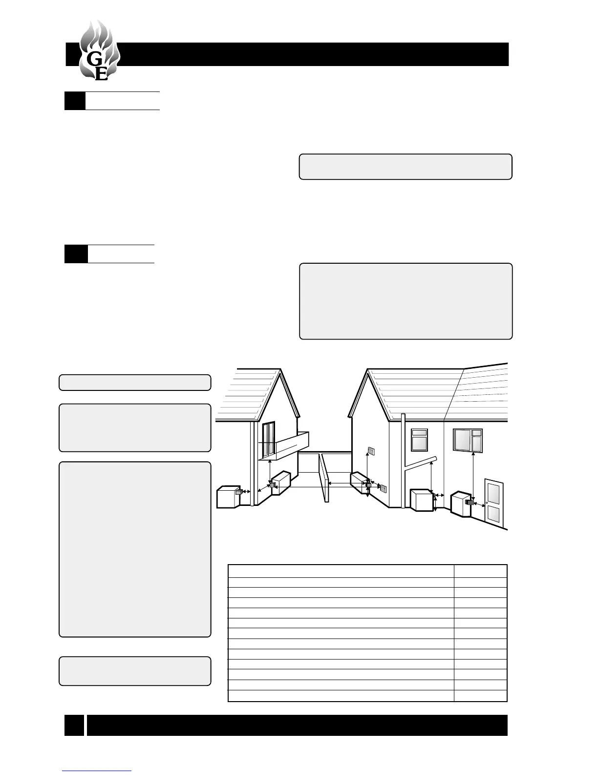
Fig. 3 - Flue terminal positions
K
D
F
AJ
B
L
G
C
C
I
H
E
A Below gutters, eaves or balconies (with protection)
B Horizontally from a door, window or air vent
C Above ground, flat roof or balcony level
D Below gutters, eaves or balconies (without protection)
E From an external corner
F From a terminal facing the terminal
G From a surface facing the terminal
H Vertically from a terminal on the same wall
I Horizontally from a terminal on the same wall
J Directly below an opening, air brick, window, etc.
K From a vertical drain pipe or soil pipe
L From an internal corner
*600
600
**300
*600
300
1200
600
1500
750
600
300
300
Terminal position Min. distance
Distances measured to rim of terminal.
Clearances recommended by Grant
Engineering (UK) Limited in
accordance with British Standards
and Building Regulations.
Notes:1 An opening means an
openable element, such as an
openable window, or a
permanent opening such as a
permanently open air vent.
2 Notwithstanding the
dimensions given, a terminal
should be at least 300 mm
from combustible material,
e.g. a window frame.
3 A way of providing
protection of combustible
material would be to fit a
heat shield at least 750 mm
wide.
Notes: * 75 mm with protection.
** 300 mm British Standards.