Combi 90 Outdoor Module
14
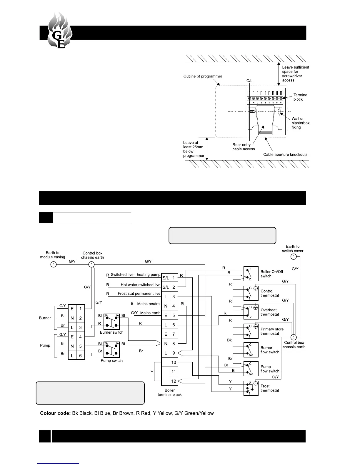
Fig. 8
5 - WIRING DIAGRAMS
4 - BOILER INSTALLATION
Control panel wiring diagram
5.1
Refer to Notes in Section 4.6.
Note: If a single channel timer is used, a link
must be fitted between terminals 2 and 3.
If a room thermostat is fitted, it must be wired
in series with the time control and the boiler
terminal S/L 1.
10 Set the left hand rocker switch to 'OFF', check that
the heating goes off and that the hot water
operation stays on.
11 Set the right hand rocker switch to 'OFF' and check
that both services do not operate.
12 Finally, return the left rocker switch to 'TIMED' and
the right hand rocker switch to the 'ON' position.