9
Combi 90 Outdoor Module
3 - GENERAL BOILER INFORMATION
General - Grant boilers are compatible with both
copper and plastic pipe. Where plastic pipe is used it
must be of an oxygen barrier type. The first metre of
pipe connected to the boiler must be made in copper.
Sealed systems - Where a sealed heating system is
fitted to the boiler only copper tube may be used.
1 Carefully remove the packaging from the boiler
and lift it off the pallet.
2 The flue terminal guard is supplied loose inside the
packaging.
3 Remove the case top panel (four screws).
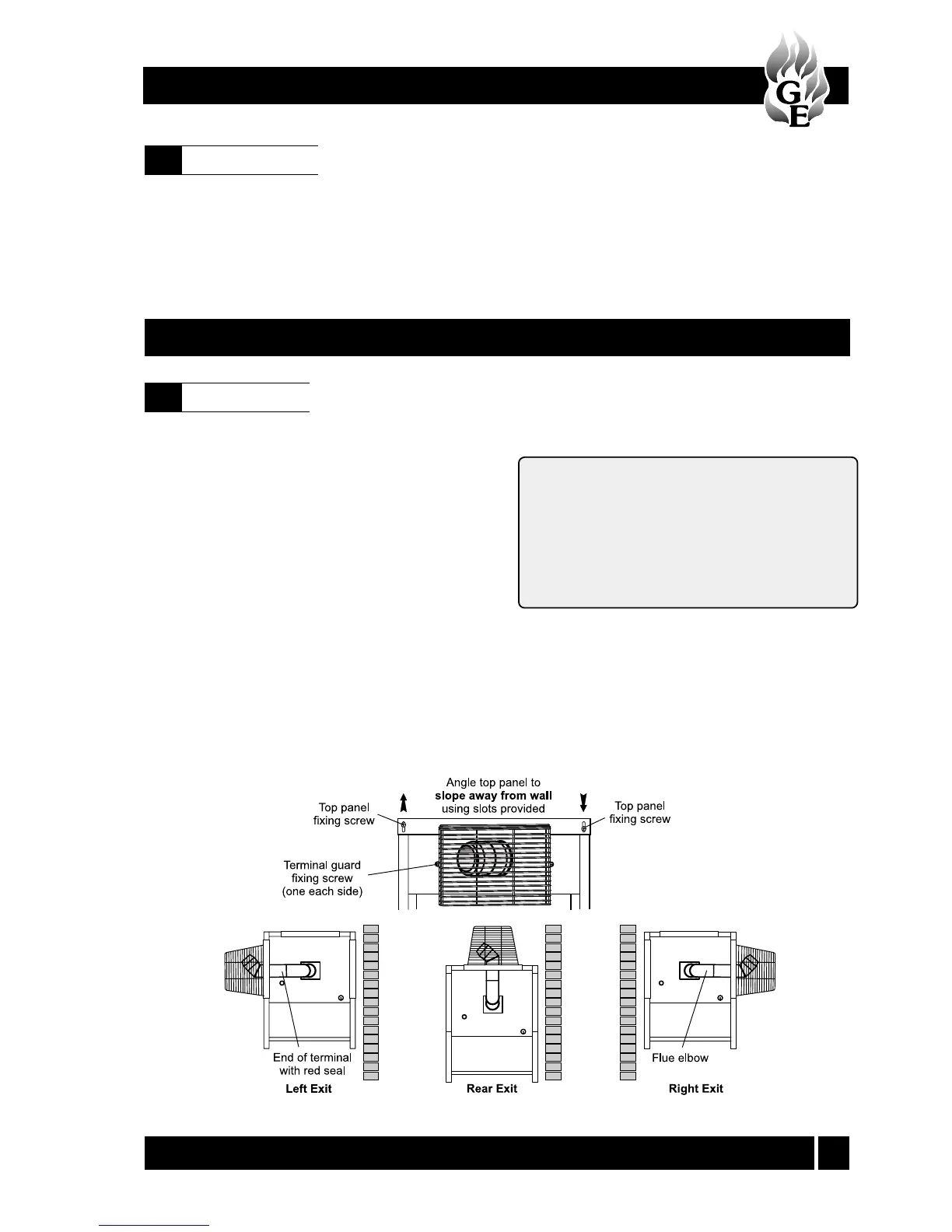
4 The flue may exit the casing from the left, right or rear
of the casing. The casing has two removable blanking
panels and a flue exit panel. Fit the panel with the flue
exit hole and seal in the required position.
5 Slacken the wing nuts holding the flue elbow and
rotate the elbow to the required direction for the
flue to exit the casing.
6 Push the end of the flue terminal section with the
red seal through the seal in the casing. The terminal
has been factory lubricated. Take care not to
dislodge or damage the red seals.
Fig. 4
Unpack the boiler
4.1
Pipework materials
3.10
4 - BOILER INSTALLATION
Underfloor systems - Plastic pipe may be used on
underfloor systems where the plastic pipe is fitted after
the thermostatic mixing valve. Copper tube must be
used for the primary pipework between the boiler and
the underfloor mixing/blending valves.
7 Carefully insert the terminal into the flue elbow until
the bend of the terminal contacts the outer casing,
then, pull the terminal forward approximately 25 mm
and rotate the bend so that the outlet is horizontal.
Rear Exit - The flue must discharge away from the
building.
Side Exit - The flue should discharge towards the
rear of the casing to prevent flue gases re-entering
the boiler casing through the air inlet vents on the
casing front door.
The flue terminal must be fitted horizontally to
prevent dripping from the end of the terminal.
8 Tighten the wing nuts holding the flue elbow and fit the
stainless steel flue guard using the two screws provided.
9 The top panel of the casing has been designed so that
it may be fitted to create a slight slope away from the
side positioned against the wall. To tilt the top panel,
loosen the four top panel casing screws, one at each
corner and push down on the side furthest from the
wall. Tighten the screws. See Fig. 4.