In-Roof System
Installation
31
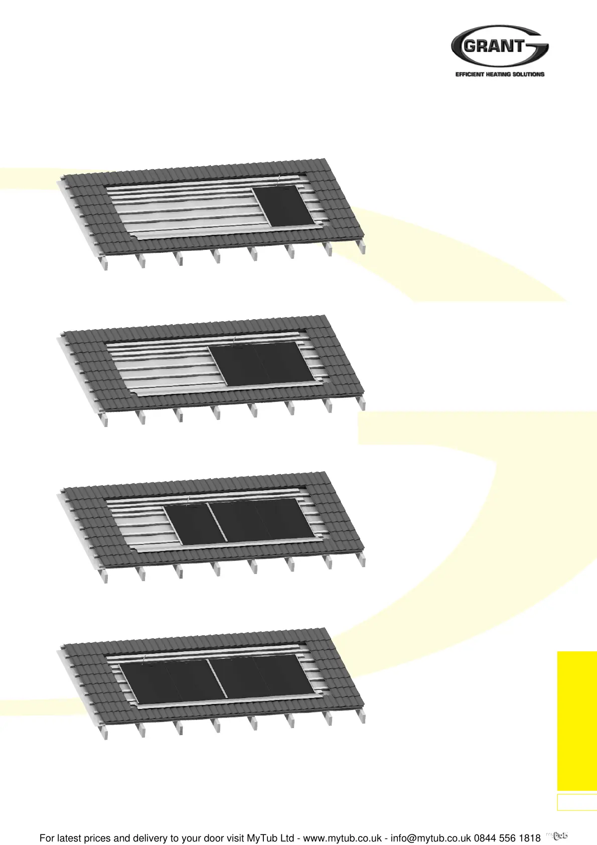
For ‘Landscape’ installations
(refer to page 25)
5. Fit first right hand (RH) half base
tray (10-B) with upwards facing
return fold towards centre. Position
side of RH half base tray at
distance ‘C’ from end of bottom
flashing with lower edge along the
fold line of the bottom flashing –
see figure 56c. Fix to middle batten
(02) using one of the self-drilling
sealing screws provided in the
installation kit at the centre of the
upper edge – see Figure 58a.
Fit first left hand (LH) half base tray
(10-A), hooking the downwards
facing return fold into the
corresponding fold on the fixed RH
half base tray. Position LH half base
tray with lower edge along the fold
line of the bottom flashing. Fix to
middle batten using one of the self-
drilling sealing screws provided in
the installation kit at the centre of
the upper edge – see Figure 58b.
6. Fit second RH half base tray. As
with the first tray, position it with the
lower edge along the fold line of the
bottom flashing. Ensure gap
between trays does not exceed
4mm – see Figure 57c. Fix to
middle batten using one of the self-
drilling sealing screws provided in
the installation kit at the centre of
the upper edge – see Figure 59a.
Fit second LH half base tray –
hooking over fold on RH half base
tray, with lower edge along fold line
of bottom flashing. Fix with a single
screw as before – see Figure 59b.
For installations using more than
two collectors, repeat the above
procedure to fit further RH and LH
half base trays as necessary.
Figure 58a: Installation of First Tray
Figure 58b: Installation of Second Tray
Figure 58c: Installation of Third Tray
Figure 58d: Installation of Fourth Tray