24
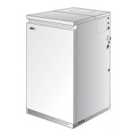
Grant Vortex Oil Boilers
4 - GENERAL BOILER INFORMATION
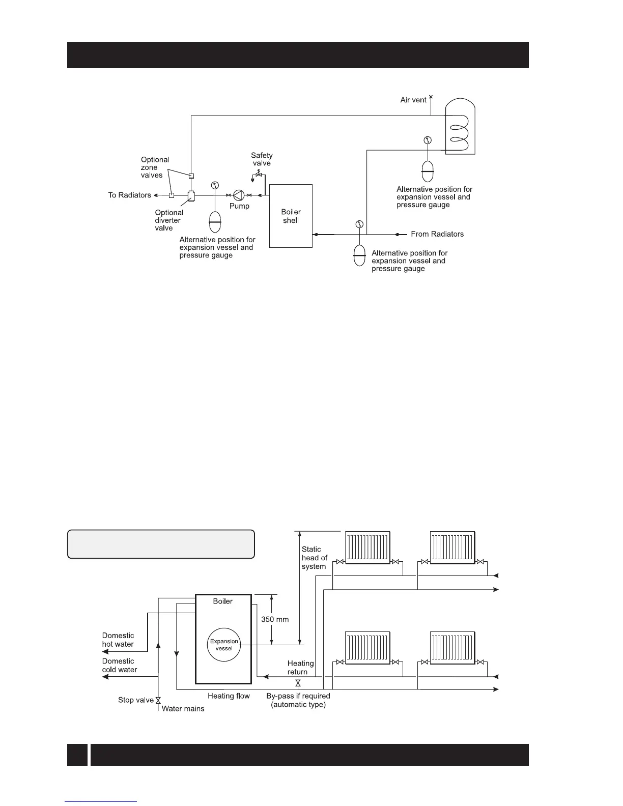
Fig. 13 - Sealed system
6 Provision should be made to replace water lost
from the system. This can be done manually (where
allowed by the local water undertaking) using an
approved filling loop arrangement incorporating a
double check valve assembly (as supplied fitted on
System models).
7 An automatic air vent should be fitted to the
highest point of the system.
8 The system design pressure (cold) should be between
0.5 and 1.0 bar. This pressure is equivalent to the
maximum static head (see Fig. 14) in bar + 0.3 (1 bar
= 10.2 metres of water).
9 If thermostatic radiator valves are fitted to all
radiators, a system by-pass must be fitted. The by-
pass must be an automatic type.
Fig. 14 - Sealed system boilers
If thermostatic radiator valves are fitted, the
system must incorporate an adequate by-pass.
10 Filling of the system must be carried out in a
manner approved by the local Water Undertaking.
Where allowed, the system may be filled via the
filling loop supplied (the loop arrangement
includes a double check valve assembly).
11 All fittings used in the system must be able to
withstand pressures up to 3 bar.
12 Radiator valves must comply with the requirements
of BS 2767(10):1972.
13 One or more drain taps (to BS 2879) must be used
to allow the system to be completely drained.
14 The expansion vessel is connected via a flexible
hose to allow it to be moved to gain access to the
baffle cleaning cover. When replacing the vessel,
care should be taken to ensure that the flexible
connecting hose is not twisted.