25
Grant Vortex Oil Boilers
4 - GENERAL BOILER INFORMATION
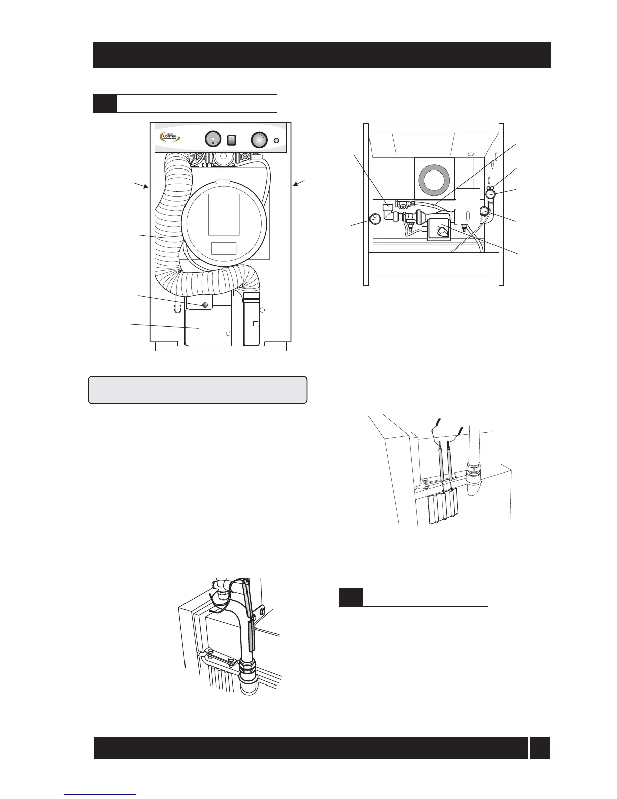
Fig. 15 - Vortex 26/36 Utility System model shown
Boiler components - System models
4.14
Top view
Burner
Lock-out
button
Air supply
tube
Heating return
(not shown)
Automatic
air vent
Automatic
air vent
Heating flow
Condensate
drain outlet
(not shown)
Circulating
pump
Pressure
relief valve
Thermostat
bulbs
Filling loop
All System models have the following sealed system
components factory fitted (refer to Fig. 15):-
a A diaphragm expansion vessel complying with
BS 4814, pre-charged at 1.0 bar. Refer to
Section 3.2.
b System pressure gauge, with an operating range
of 1 to 4 bar.
c Pressure relief safety valve complying with
BS 6759 and set to operate at 2.5 bar.
d Automatic air vent, fitted to the flow pipe of the
boiler, ensures the boiler is vented.
e Filling loop. This must be isolated and
disconnected after filling the system.
3 Refer to Section 3.2 for system volume and BS
7074: for further guidance. Refer to Section 5.6 for
further details of the expansion vessel.
On underfloor systems it is essential that the return
temperature must be maintained above 40° C to
prevent internal corrosion of the boiler water jacket.
Underfloor heating systems
4.15
Fig. 16 - Thermostat phial position - 15/26 only
Fig. 15a Thermostat phial position - 26/36 only
26/36 System
boiler shown.
For non system boilers
pockets are on side of pipe.