31
Grant Vortex Oil Boilers
Expansion vessel pressure - System models
5.6
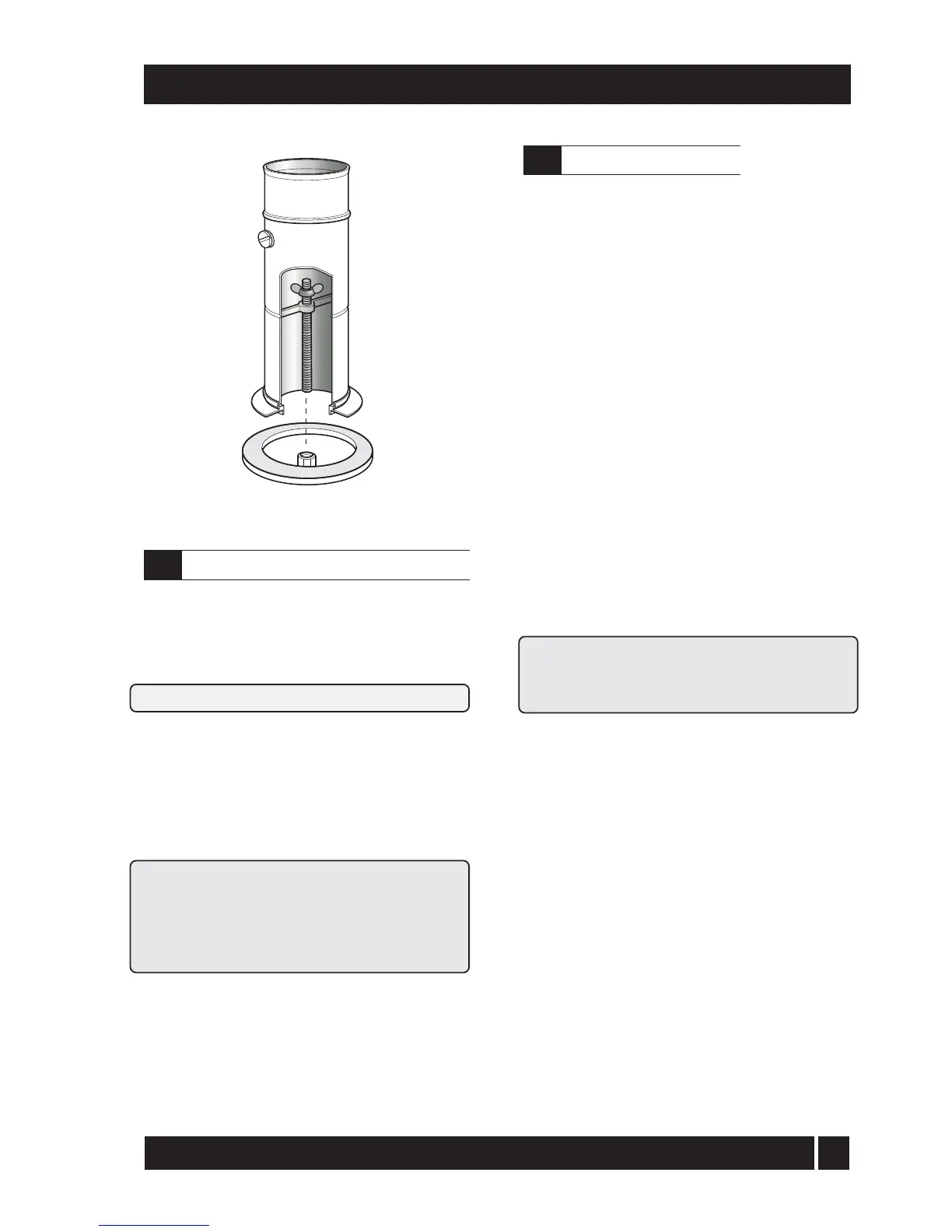
Fig. 21 - Boiler flue connector
5 - BOILER INSTALLATION
The expansion vessel fitted, is supplied with a charge
pressure of 1.0 bar (equivalent to a max. static head of
10.2 metres). The charge pressure must not be less
than the actual static head at the point of connection.
Do not pressurise the vessel above 1.5 bar.
The air pressure in the vessel must be checked annually.
The central heating system volume, using the expansion
vessel as supplied, must not exceed the recommended
volumes. If the system volume is greater, an extra
expansion vessel (complying with BS 4841) must be
fitted as close as possible to the central heating return
connection on the boiler. The charge pressure of the extra
vessel must be the same as the vessel fitted in the boiler.
Refer to BS 7074:1 for further guidance.
The air charge pressure may be checked using a tyre
pressure gauge on the expansion vessel Schraeder
valve. The vessel may be re-pressurised using a
suitable pump. When checking the air pressure the
water in the heating system must be cold and the
system pressure reduced to zero.
It is recommend that the boiler should be connected to
a switched mains power supply from a programmer or
control system. If a Grant plug-in programmer is used,
a permanent 240 V mains supply (fused at 5 Amp)
must be taken to the boiler. A three core cable is
required to connect the boiler terminal block to the
live supply. Refer to Sections 9.5 and 9.6 for typical
control system wiring diagrams.
1 Lift off the boiler case top panel, if it has not
already been removed.
2 Remove the top of the control panel (Utility
models) or the wiring cover (on Kitchen models)
and open the cable clamp. Route the supply cable
through the hole in the rear panel (using the
grommet supplied) up to the control panel, pass it
through the cable clamp and connect to the boiler
terminal block (refer to Section 9) as follows:-
Brown to live (terminal 1)
Blue to mains neutral (terminal 2)
Green/Yellow to mains earth (terminal 3)
Kitchen and Kitchen System models - If the plug-in
programmer is not fitted, ensure that the RED wire
link, between terminals 1 and 8 (1 and 10 on System
model) on the boiler terminal block is fitted.
Note: Ensure that the route and length of the cable
is such that the boiler front cover plate can be
easily removed without disconnecting the supply
cable from the terminal block.
3 If the optional plug-in electronic programmer is to
be fitted, follow the fitting instructions given in
Section 5.8 at this point.
4 Secure the cable in the cable clamp.
5 Place the wiring cover in position over the terminal
block, taking care not to trap any wires and secure
in position with the two M4 screws provided.
6 Ensure that all external wiring is adequately supported.
Do not switch on the electricity supply at this stage.
Connect the power supply
5.7