40
Grant Vortex Oil Boilers
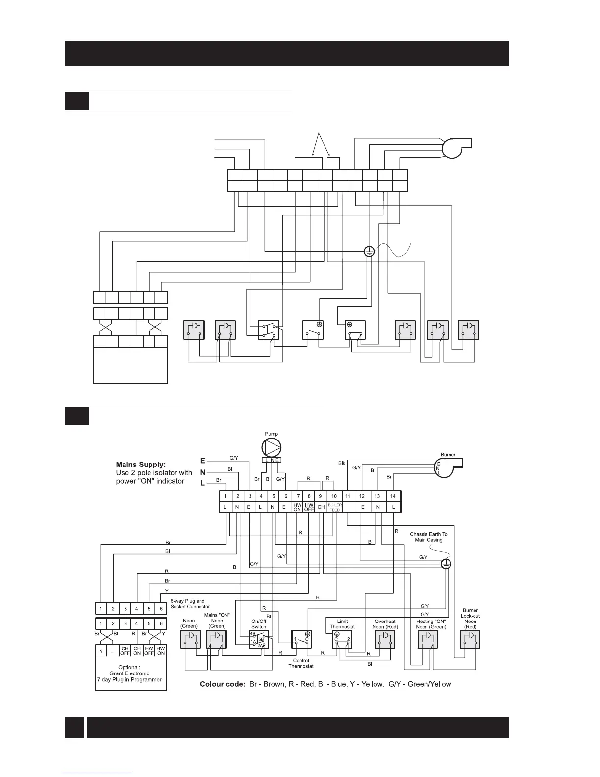
9 - WIRING DIAGRAMS
Fig. 31
Control panel wiring diagram - Kitchen models
9.1
Control panel wiring diagram - Kitchen System models
9.2
Fig. 32
Colour code: Br - Brown, R - Red, Bl - Blue, Y - Yellow, G/Y - Green/Yellow, Blk - Black
12
3
4
56
7
8910
11 12
LNE EN L
HW
ON
HW
OFF
CH
BOILER
FEED
123456
1
C
C
2
Control
Thermostat
Limit
Thermostat
Heating
"ON"
Neon
(Green)
On/Off
Switch
Chassis Earth To
Main Casing
NL
CH
OFF
CH
ON
HW
OFF
HW
ON
Optional:
Grant Electronic
7-day Plug-in Programmer
6-way Plug and
Socket Connector
L
E
N
Burner
Mains Supply:
Use 2 pole isolator
with power "ON" indicator
E
N
L
G/Y
Bl
Br
G/Y
Bl
Br
R
R
R
R
R
Br
G/Y
G/Y
R
R
R
Bl
Bl
Y
R
Bl
Bl
Br
Br Bl YBrR
G/Y
G/Y
4B
5B
1A
2A
Blk
Burner
Lock-out
Neon (Red)
Mains "ON"
Neon
(Green)
Overheat
Thermostat
123456
Neon
(Green)
Note: Remove both links
if plug-in programmer is fitted