Electrical
23
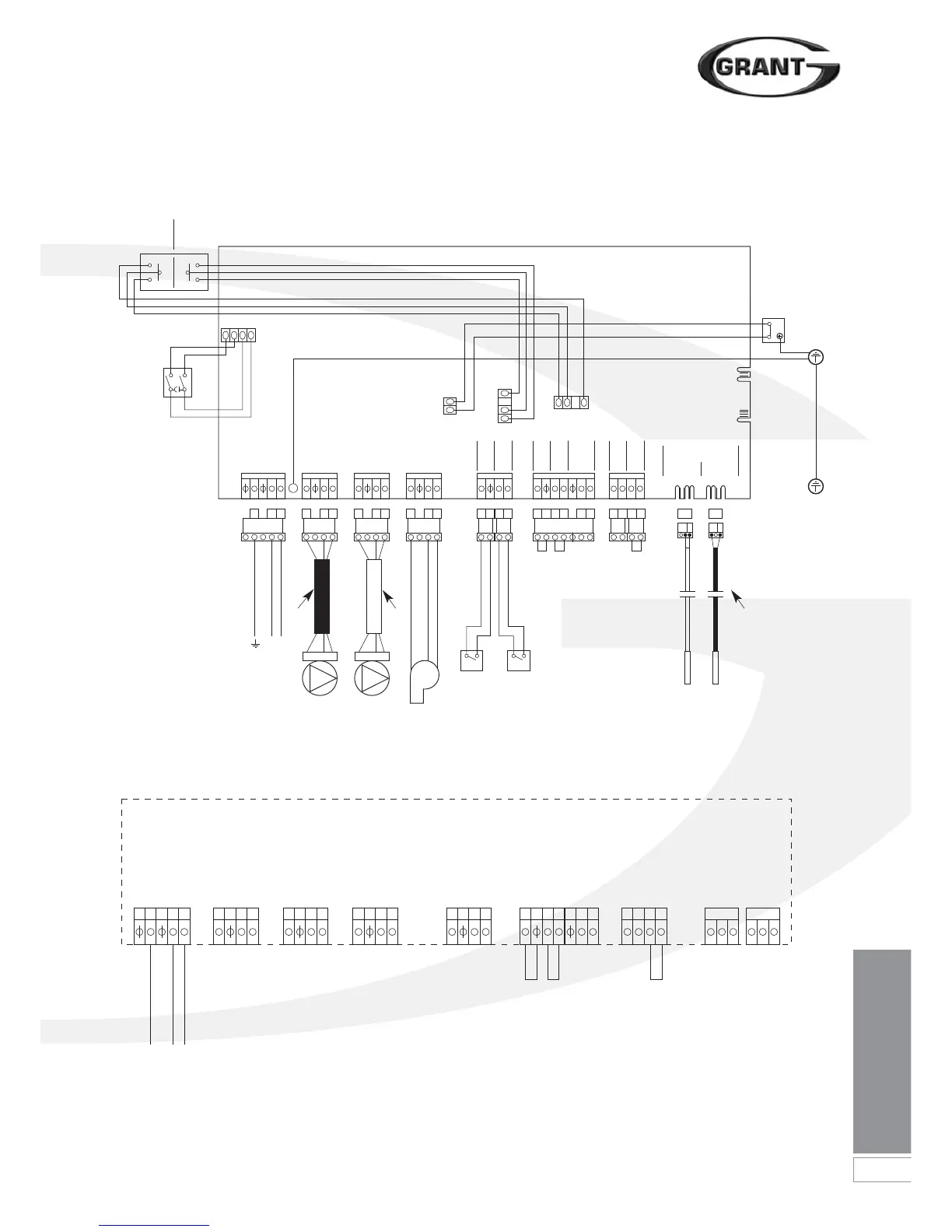
Figure 8-2: Vortex Pro Combi e wiring terminals
Figure 8-1: Boiler wiring diagram
8 Electrical
Central
Heating
Switch
Domestic
Hot Water
Switch
4B
BL
BR
GR
GR
G/Y
BL
Timer
Colour code:
BR - Brown
BL - Blue
RD - Red
G/Y - Green/Yellow
BLK - Black
OR - Orange
Y - Yellow
GR - Grey
BR
Const
Off Off
Timed
Const
Timed
5B
4B
5B
1A
2A
6B
123
123 456 789 101112 13141516 1718 212219 20 23 24 27 2825 26
ENL
ENL ENL
E
N
L
NL
456
ENL
789
ENL
10 11 12
ENL
RD ORBLK
13 14 1516 23 24 25 26 27 28171819 20 21 22
Mains CH Pump DHW Pump Burner
Low Press
Switch
Flow
Switch
CH
Timed on
Timer Neutral
Timer Live
DHW
Timed on
Room Stat (from)
Thermistors
Store Flow
Ext Frost Stat (from)
Ext Frost Stat (to)
Electrical Mains
Connection Plug
Boiler Control Panel - PCB Connections
Printed Circuit Board
230V 5A Fused
Supply
ENL
NEL
Mains
CH Pump Earth
CH Pump Neutral
CH Pump Live
DHW Pump Earth
DHW Pump Neutral
DHW Pump Live
Burner Pump Earth
Burner Pump Neutral
Burner Pump Live
Flow Switch
Flow Switch
Pump Switch
Pump Switch
Ext. Frost Stat
Orange
Black
Red
Ext. Frost Stat
Store Thermistor
Flow Thermistor
Room Stat
Room Stat
Timer Neutral
Timer Live
DHW Timer On
CH Timer On
230V 5A Fused
Supply
CH
Pump
Black
Cable
DHW
Pump
Flow
Switch
No No
Pressure
Switch
Store
Thermistor
Flow
Thermistor
Burner
White
Cable
Black shroud
indicates flow
thermistor
Earth connection
boiler top bracket
Limit
Thermostat
G/Y
G/Y
2
C