38
Flue System and
Air Supply
9 Flue System and Air Supply
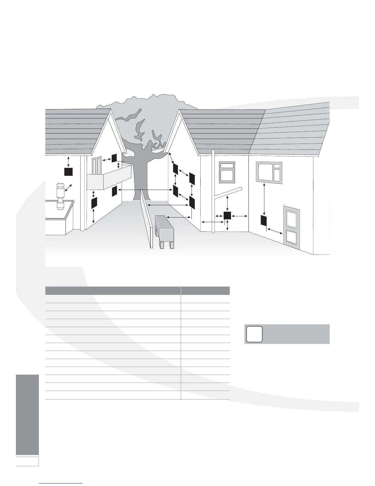
Figure 9-11: Clearances for Balanced flue terminals
The minimum distances as shown in Figure 9-11 are given in the table below:
Terminal position Min. distance (mm)
A Below a gutter or sanitary pipework 600*
B Horizontal from an opening, air brick or window 600
C Above ground or balcony level 300
D Below eaves or balcony 600*
E From an internal or external corner 300
F From a terminal facing the terminal 1200
G From a surface facing the terminal 600
H Vertical from terminals on the same wall 1500
I Horizontal from terminals on the same wall 750**
J Below an opening, air brick, window, etc. 600
K From vertical sanitary pipework 300
L Vertical flue from wall 750
M From an oil storage tank 1800
Notes:
* 75mm with protection.
** Only applies if one or both terminals are balanced flues.
D
D
L
C
C
B
B
B
D
F
E
K
A
E
C
G
M
J
J
H
I
1. An opening means an openable
element, such as an openable
window, or a permanent opening
such as a permanently open air
vent.
2. Notwithstanding the dimensions
given, a terminal should be at
least 300mm from combustible
material, e.g. a window frame.
3. A way of providing protection of
combustible material would be to
fit a heat shield at least 750mm
wide.
!
NOTE
Distances measured to rim of terminal.
Clearances recommended by Grant
Engineering (UK) Limited in accordance
with British Standards and Building
Regulations.