Connect the output side of the AC adapter to the
connector indicated as "DC LINE" on the GL220.
Connect the output side of the AC adapter to the
connector indicated as "DC LINE" on the GL220.
Use a flathead screwdriver to push the button above the
ground terminal while connecting the grounding cable to the
GL220. Connect the other end of the cable to ground.
Grounding cable
Note: Connect wires to the desired terminals according to the terminal numbers on
top of the terminal block.
Direct voltage input Thermocouple inputDirect current input
CH 1 2 3 4 5 6 7 8 9 10
Shunt resistance
Ex: for current in the 4 to 20 mA
range, apply a resistance of 250 W
(±0.1%) and perform measurement
in the 1 to 5 V range.
Note: Use B-551 (option)
for this shunt resistance.
+
-
Compensation
copper wire
+
-
Direct voltage
+
-
Direct voltage
Note: Connect wires to the desired terminals according to the terminal numbers on
top of the terminal block.
*B-513 (sold separately) cable is required for external input/output.
(For logic/pulse input, alarm output, trigger input, external sampling input
B-513
Orange with red dotted line : 1
Orange with black dotted line : 2
Grey with red dotted line : 3
Grey with black dotted line : 4
White with red dotted line : 1
White with black dotted line : 2
Yellow with red dotted line : 3
Yellow with black dotted line : 4
Pink with red dotted line : Trigger input/
external sampling input
Shielded
GND
Logic/pulse
input
Alarm output
Connection diagram
Pink with black dotted line
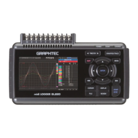
GL220 Connection Procedures
Connecting the AC Adapter
Connecting the Grounding Cable
Making Connections to the Analog Input Terminals
3
Making Connections to the External Input/Output Terminals